Inner Range Inception Installation Manual
Hide thumbs
Also See for Inception:
- Quick start manual (4 pages) ,
- Quick start manual (4 pages) ,
- Quick start manual
Table of Contents
Advertisement
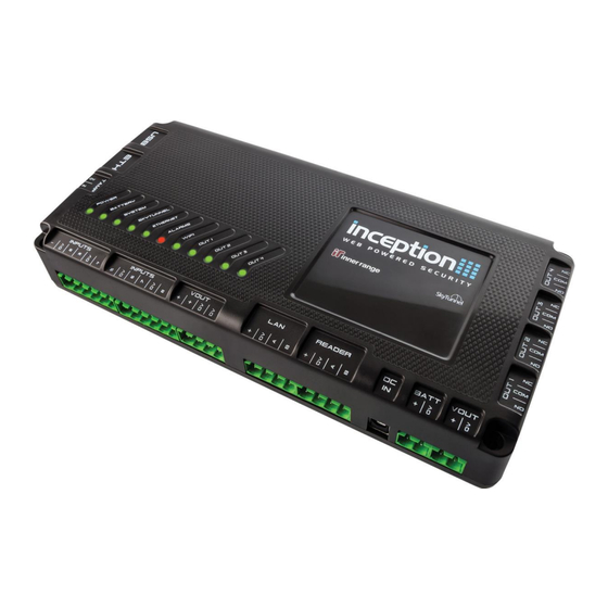
Inner Range Inception Security Controller
Installation Manual. Rev. 4.0
Inception Controller
by Inner Range
P/N: 996300
V4 Installation Manual
(Current to Firmware V4.0 and Controller PCB Rev. E)
BEFORE COMMENCING INSTALLATION
PLEASE READ THE IMPORTANT NOTES ON PAGE 3.
Document P/No: 636300
1
© 2016 - 2020. Inner Range Pty Ltd.
www.innerrange.com
Advertisement
Table of Contents

Subscribe to Our Youtube Channel
Related Manuals for Inner Range Inception


Summary of Contents for Inner Range Inception
- Page 1 Inner Range P/N: 996300 V4 Installation Manual (Current to Firmware V4.0 and Controller PCB Rev. E) BEFORE COMMENCING INSTALLATION PLEASE READ THE IMPORTANT NOTES ON PAGE 3. Document P/No: 636300 © 2016 - 2020. Inner Range Pty Ltd. www.innerrange.com...
-
Page 2: Table Of Contents
Report Mapping ......................... 17 TROUBLESHOOTING...................... 18 MAINTENANCE........................ 20 Firmware update ........................20 Reboot/Default the Inception Controller..................21 Specifications ........................22 Power supply outputs......................23 Additional Resources ...................... 24 © 2016 - 2020. Inner Range Pty Ltd. www.innerrange.com... -
Page 3: Important Notes
Expansion modules connected to the Inception controller via the RS485 system LAN, must be connected using appropriate twisted-pair cable. If Inception is replacing another product, any existing LAN wiring may only be used if it meets the LAN cabling requirements described in the ‘LAN & Reader Ports’ section of this manual. -
Page 4: Introduction
• 12V DC power outputs for powering external security devices. • LAN port for system expansion via RS-485. • Reader port for connection of up to 8 x Inner Range SIFER or SIFER-Keypad readers. • DC power input for connection to the Inception power supply. -
Page 5: System Capacities
DOTL, valid & invalid (for wiegand readers), lift floor button enables, siren outputs, strobes, automation devices, etc. The Inception controller has 4 relay outputs in total. These can be used as lock relays for doors, floor button enable contacts for lifts or general purpose dry contact outputs. -
Page 6: Accessories List
* Does not include current required by detectors, sounders, readers, locks, LEDs and other peripheral devices connected to these modules. † UniBus expander boards can only be connected to an 8-32 Zone LAN Expander Module. © 2016 - 2020. Inner Range Pty Ltd. www.innerrange.com... -
Page 7: Installation
Widebody and Rack-mount Enclosures. Refer to the Inner Range website. Power Supply Options The Inception controller has connections for an 18 to 24V DC Power Supply input and a 12V Sealed Lead-Acid (SLA) Battery. These connections are labelled “DC IN” and “BATT” respectively and allow two power supply options to be supported: 1. -
Page 8: Wireless Devices
(for reed switches, etc.) and wireless remote fobs. When RF transmitter activity is saved to the Inception review log, a signal strength value is included in the message. This allows the installer to assess the relative signal strength of different receiver and/or transmitter locations and the effective range of portable transmitters such as remote fobs. -
Page 9: Installation Procedure
8. When programming and commissioning of the system is complete, and whenever programming changes are made, use the browser to create a backup of the Inception controller database. Use the “Backup Database” option in the Backup/Restore section of the System options. -
Page 10: Led Status Indicators
Inner Range Inception Security Controller Installation Manual. Rev. 4.0 LED Status Indicators The Inception controller has 11 status LED’s to quickly identify the current operational status. LED State Meaning POWER No DC IN connected. (Mains not present) ON Green DC IN connected (Mains power present) and within nominal voltage range. -
Page 11: Wiring Diagrams
Non-Inductive Loads. e.g. 12V Sounder, Beeper, Strobe, LED, etc. The Inception power supply may be used to power these devices. Check that the additional current required by these devices does not cause the Inception power supply output limits to be exceeded. © 2016 - 2020. Inner Range Pty Ltd. -
Page 12: Zone Inputs
Please check the manufacturer’s documentation. Example: Reed Switch. Tamper Input. For tamper switches provided with the recommended enclosures, select “Open Circuit Secure” in the Controller hardware settings in the browser. © 2016 - 2020. Inner Range Pty Ltd. www.innerrange.com... -
Page 13: Lan & Reader Ports
Approx 200m for an LCD Terminal; Approx. 25-50m for other Module types. See the “Inception LAN Installation Guide” for details. If a separate power supply is used, do not connect + from the controller Reader port to the Module. -
Page 14: Lan And Reader Installation Diagrams
The installation requirements are illustrated in the drawings below and on the following page. The characters in square brackets reference the various points in the lists on the previous page. LAN wiring detail [6] Shielded, twin, twisted-pair data cable LAN network overview © 2016 - 2020. Inner Range Pty Ltd. www.innerrange.com... - Page 15 [6] Shielded, twin, twisted-pair data cable SIFER or SIFER-Keypad Reader connection overview [I] Any Reader more than 100m from the Controller may require a [III] separate local battery-backed power supply &/or heavier gauge cable. [II] © 2016 - 2020. Inner Range Pty Ltd. www.innerrange.com...
-
Page 16: Usb Port
Wi-Fi enabled device to connect to the network. By default, the name of the Wi-Fi network will be the Inception controller serial number (e.g. WS001923) with the password “inception”. Open a browser and navigate to the URL http://inception.local... -
Page 17: Alarm Reporting
Central Monitoring Station. T4000 Communicator A T4000 Security Communicator can be connected to the USB port on the Inception controller to send IP alarms to a Monitoring Station in Contact ID or IR-fast reporting formats.* T4000 can provide multiple redundant polled reporting paths using multiple 3G networks in addition to ethernet internet reporting to ensure reliable alarm monitoring. -
Page 18: Troubleshooting
The installer user Perform an Installer User Password reset. with any user, or credentials were lost, or a access is restricted web profile change has limited everyone’s access with all users. © 2016 - 2020. Inner Range Pty Ltd. www.innerrange.com... - Page 19 “Get time out of order. configured NTP server is from browser“. This will sync the inception not configured correctly. panel’s time to that of the device being used to setup the system.
-
Page 20: Maintenance
Installation Manual. Rev. 4.0 MAINTENANCE. Firmware update The Inception controller and LAN Modules can be updated to the latest firmware version from the browser. Use the “Update Controller” or “Update Modules” selections in the Firmware Update options under “System”. See screen below. -
Page 21: Reboot/Default The Inception Controller
2) The Inception controller can be reset to the Factory Default settings from the browser. Use the “Reset to Factory Default” button in the Backup/Restore options under “System”. See screen image below. -
Page 22: Specifications
Zone inputs: 4 (‘OUT1-4’) Relay outputs: Relay contact rating: 5 Amps. 30v DC or AC. See Note 2 below. USB version: Alarm Reporting Formats: Contact ID. IR-fast. (via T4000 or SkyTunnel) © 2016 - 2020. Inner Range Pty Ltd. www.innerrange.com... -
Page 23: Power Supply Outputs
Inception controller power supply. 3. A separate external battery-backed power supply may be required for devices connected to the Inception controller if the current required is in excess of the maximum current allowed for that power supply output, or causes the maximum combined output current specification to be exceeded. -
Page 24: Additional Resources
Inception Quickstart Guide. Inception LAN Installation Guide. Inception Release Notes. Inception Installer Manual for AS/NZS 2201.1:2007 Classes 1 to 3 Compliance. Elite LCD Terminal / EliteX LCD Keypad Installation manuals. Integriti SIFER Smart Card Reader / SIFER-Keypad Installation manuals. Integriti Expansion Module installation manuals. (SLAM, 8-Zone Exp., RF Exp. etc.) Integriti Power Supply installation manuals.
Need help?
Do you have a question about the Inception and is the answer not in the manual?
Questions and answers