Table of Contents
Advertisement
Quick Links
© 2020 TE Connectivity Ltd. family of companies.
All Rights Reserved.
*Trademark
TE Connectivity, TE connectivity (logo), and TE (logo) are trademarks. Other logos, product, and/or company names may be trademarks of their respective owners.
Heavy Duty Electric
Hydraulic Pumps
PN 69120-1 and 69120-2
SAFETY PRECAUTIONS - AVOID INJURY - READ THIS FIRST! ...................................... 2
1. INTRODUCTION .................................................................................................................. 3
2. DESCRIPTION ..................................................................................................................... 4
2.1.Physical .......................................................................................................................... 4
2.2.Functional ....................................................................................................................... 4
2.3.Specifications ................................................................................................................. 4
2.4.Accessories .................................................................................................................... 7
3. RECEIVING INSPECTION ................................................................................................. 10
4. SETUP ................................................................................................................................ 10
4.1.Installing the Casters .................................................................................................... 10
4.2.Filling the Hydraulic Fluid Reservoir ............................................................................. 11
4.3.Preparing the Hydraulic Connections ........................................................................... 11
4.4.Connecting the Accessories ......................................................................................... 12
4.5.Disconnecting Accessories .......................................................................................... 14
5. OPERATING PROCEDURE .............................................................................................. 15
5.1.Precautions .................................................................................................................. 15
5.2.Crimping ....................................................................................................................... 16
6. MAINTENANCE AND INSPECTION ................................................................................. 17
6.1.Storage ......................................................................................................................... 18
6.2.Hydraulic Fluid Reservoir ............................................................................................. 18
6.3.Bleeding Air from Hydraulic System ............................................................................. 19
6.4.Checking Hydraulic Pressure ....................................................................................... 20
6.5.Checking and Replacing Brush Assembly on Universal Motor .................................... 21
7. DISPOSAL ......................................................................................................................... 21
8. REPLACEMENT AND REPAIR ......................................................................................... 22
9. RESTRICTION ON HAZARDOUS SUBSTANCES (RoHS) INFORMATION .................... 22
10. REVISION SUMMARY ....................................................................................................... 22
PRODUCT INFORMATION 1-800-522-6752
This controlled document is subject to change.
For latest revision and Regional Customer Service,
visit our website at www.te.com.
Customer Manual
409-1950
Rev G
8 DEC 20
1 of 22
Advertisement
Table of Contents

Related Manuals for TE Connectivity 69120-1

Summary of Contents for TE Connectivity 69120-1
-
Page 1: Table Of Contents
1 of 22 For latest revision and Regional Customer Service, All Rights Reserved. visit our website at www.te.com. *Trademark TE Connectivity, TE connectivity (logo), and TE (logo) are trademarks. Other logos, product, and/or company names may be trademarks of their respective owners. -
Page 2: Safety Precautions - Avoid Injury - Read This First
409-1950 SAFETY PRECAUTIONS — AVOID INJURY — READ THIS FIRST! Safeguards are designed into this application equipment to protect operators and maintenance personnel from most hazards during equipment operation. However, certain safety precautions must be taken by the operator and repair personnel to avoid personal injury, as well as damage to the equipment. For best results, application equipment must be operated in a dry, dust-free environment. -
Page 3: Introduction
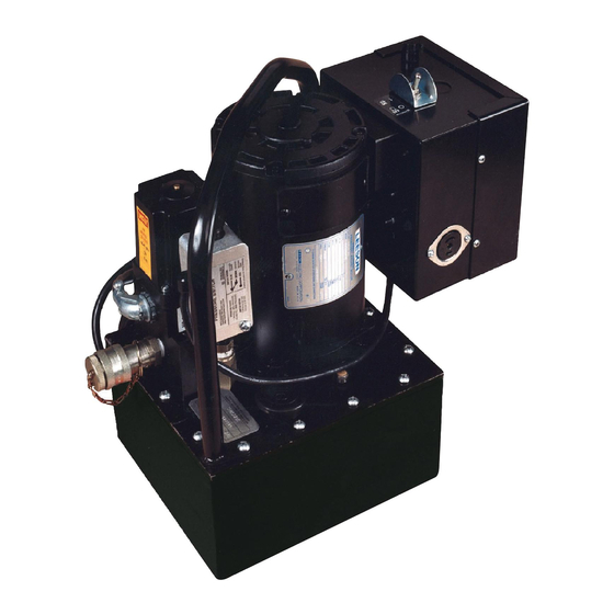
409-1950 Figure 1: Heavy-duty electric hydraulic pump 1. INTRODUCTION Each heavy-duty electric hydraulic pump (shown in Figure 1) is a portable power source that uses a handle control or foot control to activate the unit. The unit combines the convenience of a hand tool with the power of a large machine used for the application of terminals and splices onto large wire sizes. -
Page 4: Description
The pump features a pilot lamp (69120-1 only) that illuminates to indicate that the pump is activated. The pump includes casters (one for each corner) that can be installed onto the pump for portable applications. - Page 5 409-1950 Table 3: Oil delivery rate Oil pressure Oil delivery per minute Liters Cubic inches 10.7 1000 5000 8400 Figure 2 shows the oil delivery rate at different pressure levels. Figure 2: Performance curve for oil pressure vs. volume 5 of 22 Rev G...
- Page 6 409-1950 Table 4: Other specifications 839 W [11/8 hp] 50-60 Hz, single phase Motor 8400 rpm Current draw (max) 14 A (15 A circuit breaker) Noise (at idle and max pressure 90-95 dBA output) Pressure output 579 bar [8400 psi] max Reservoir capacity 7.57 liters [2 gallons] Pressure switch setting...
-
Page 7: Accessories
409-1950 2.4. Accessories The accessories for the pump shown in Figure 3 are available separately. The pump accepts interchangeable crimping heads, and the crimping heads accept interchangeable die assemblies, except Crimping Head 69069 (which has self-contained dies). Use of a latch pin kit eliminates the possibility of misplacing the standard latch pin supplied with the crimping head. - Page 8 409-1950 Hydraulic Handle Control Assembly The handle control assembly consists of a handle grip, an outlet with a female quick-disconnect coupler and protector cap, and a cordset. It is available with or without a hose assembly. The handle control is operated by three switches (marked RUN, DUMP, and RESET).
- Page 9 409-1950 Multi-Directional Valve The multi-directional valve features a manual handle control and outlets to connect more than one head to the pump (up to three or six is available). The valve can only be operated by the foot control. Installation and operating procedures are provided in the instruction sheet packaged with the valve.
-
Page 10: Receiving Inspection
1. Carefully inspect the pump upon arrival for evidence of damage that may have occurred in transit. If damage is evident, file a claim against the carrier and notify TE Connectivity. 2. Check all components to make sure that they are secure. -
Page 11: Filling The Hydraulic Fluid Reservoir
409-1950 4.2. Filling the Hydraulic Fluid Reservoir The pump is shipped without oil in the hydraulic fluid reservoir. The proper oil to be used is included with the pump in a separate container. Fill the reservoir as follows: DANGER Always use proper eye protection and oil-resistant gloves when handling hydraulic fluid. 1. -
Page 12: Connecting The Accessories
409-1950 4.4. Connecting the Accessories CAUTION Before installing any accessories, make sure the pump is DISCONNECTED from the power supply. Make sure that all coupling areas of the accessories being used are thoroughly clean. If Using the Handle Control 1. Attach the hose assembly. ... - Page 13 409-1950 If Using the Foot Control Refer to Figure 6. 1. Attach one end of the hose assembly to the pump. Mate the quick-disconnect couplers and tighten the collar. 2. Attach the other end of the hose assembly to the crimping head according to the instructions included with the crimping head.
-
Page 14: Disconnecting Accessories
409-1950 If Using the Multi-Directional Valve (Foot Control Must Be Used) Refer to Figure 7. 1. Attach one end of a hose assembly to the pump and the other end to the multi-directional valve. 2. Attach one end of each hose assembly to the multi-directional valve and the other end of each hose assembly to a crimping head according to 408-1208. -
Page 15: Operating Procedure
409-1950 5. OPERATING PROCEDURE 5.1. Precautions To avoid personal injury or damage to the pump or accessories, carefully observe the following precautions before, during, and after operation of the pump. For the power supply DANGER Ensure that the total current of the pumps being used matches the amperage of the electrical circuit being used. DANGER To avoid the possibility of fire, DO NOT attempt to increase the power line capacity by replacing a fuse with a fuse of higher value. -
Page 16: Crimping
2. Strip the wires according to the instructions included with the crimping head or die assembly. 3. Depress the RESET switch. The pilot lamp on the pump illuminates (69120-1 only). 4. Depress the RUN switch momentarily to partially extend the cylinder of the crimping head. The dies partially close. -
Page 17: Maintenance And Inspection
409-1950 6. MAINTENANCE AND INSPECTION It is important to establish a preventive maintenance and inspection program. Maintenance must be performed at regular intervals to ensure efficient, dependable performance of the pump. Maintenance should be performed in a dust-free area by a qualified technician. Any electrical work MUST be performed by a qualified electrician. -
Page 18: Storage
409-1950 6.1. Storage NEVER store the pump without having the protector cap installed or a hydraulic hose and crimping heads attached to the hydraulic connection. The pump should be stored in a clean, dry area with low humidity noncondensing). Check for proper pump function after storage. 6.2. -
Page 19: Bleeding Air From Hydraulic System
409-1950 Draining, Flushing, and Refilling the Hydraulic Fluid Reservoir The frequency of oil changes depends upon the general working conditions, severity of use, and overall cleanliness and care of the pump. It is recommended to drain, flush, and refill the reservoir of the pump with an approved hydraulic oil after approximately every 300 hours of operating the pump as follows: ... -
Page 20: Checking Hydraulic Pressure
409-1950 6.4. Checking Hydraulic Pressure Check that the pump is functioning properly and reaching the proper pressure after every eight hours of use. If necessary, adjust the pressure as follows: 1. Depress the DUMP switch to release the pressure from the system, then DISCONNECT the pump from the power supply. -
Page 21: Checking And Replacing Brush Assembly On Universal Motor
409-1950 6.5. Checking and Replacing Brush Assembly on Universal Motor To prevent premature failure of the armature, periodically check the brushes for wear as follows: 1. Depress the DUMP switch to release the pressure from the system, then DISCONNECT the pump from the power supply. -
Page 22: Replacement And Repair
Quantity per part number 3-306171-4 Brush assembly – Customer-supplied Power cord, 115 V, pump 69120-1 – Customer-supplied Power cord, 220 V, pump 69120-2 9. RESTRICTION ON HAZARDOUS SUBSTANCES (ROHS) INFORMATION Information on the presence and location of any substances subject to RoHS can be found at http://www.te.com/customersupport/rohssupportcenter.
Need help?
Do you have a question about the 69120-1 and is the answer not in the manual?
Questions and answers