
Related Manuals for GESTRA NRG 10-52


Summary of Contents for GESTRA NRG 10-52
- Page 1 Level Electrode NRG 10-52 NRG 16-52 Original Installation & EN (USA) Operating Manual 850696-00 English...
-
Page 2: Table Of Contents
Five-pole connector of the NRG 10-52, NRG 16-52 ................ 21 Connecting the level electrode ....................... 22 Assigning the five-pole connector of the NRG 10-52, NRG 16-52 ........... 22 Terminals in the contact block ....................... 22 NRG 10-52, NRG 16-52 - USA - Installation & Operating Manual - 850696-00... - Page 3 Bringing into service, fault indications and troubleshooting ............23 Taking out of service .......................... 23 Disposal .............................. 24 Returning decontaminated equipment ....................24 UL components ........................... 24 NRG 10-52, NRG 16-52 - USA - Installation & Operating Manual - 850696-00...
-
Page 4: Content Of This Manual
Scope of supply, product package NRG 10-52 NRG 16-52 1 Level electrode NRG 10-52 1 Level electrode NRG 16-52 1 Installation & Operating Manual 1 Installation & Operating Manual NRG 10-52, NRG 16-52 - USA - Installation & Operating Manual - 850696-00... -
Page 5: How To Use This Manual
How to use this Manual This Installation & Operating Manual describes the correct use of NRG 10-52, NRG 16-52 level electrodes. It applies to persons who integrate this equipment in control systems, install, bring into service, operate, maintain and dispose of this equipment. Anyone carrying out the above- mentioned activities must have read this Installation &... -
Page 6: Types Of Warning
CAUTION Warning of a situation that may result in minor or moderate injury. ATTENTION Warning of a situation that results in damage to property or the environment. NRG 10-52, NRG 16-52 - USA - Installation & Operating Manual - 850696-00... -
Page 7: Specialist Terms, Abbreviations
A boiler that is operated at 145 psi (10 bar) and 356°F (180°C) may be designed to withstand a pressure of 870 psi (60 bar) and a temperature of 527°F (275°C), for example, which is therefore not necessarily its operating point. NRG 10-52, NRG 16-52 - USA - Installation & Operating Manual - 850696-00... -
Page 8: Usage For The Intended Purpose
Usage for the intended purpose In combination with NRS 1-.. level switches, the NRG 10-52, NRG 16-52 level electrode indicates when up to four different water levels have been reached. The level electrode and level switches are installed in steam boilers and hot water installations or in condensate and feedwater tanks, e.g., as a water level controller with MIN/MAX alarm. -
Page 9: Basic Safety Information
Check that the level electrode is not leaking when bringing into service. ■ Attempts to repair the equipment will cause the plant to become unsafe. The NRG 10-52, NRG 16-52 level electrode may only be repaired by the ■ manufacturer, GESTRA AG. -
Page 10: Required Personnel Qualifications
Persons trained by the plant operator to work Refits Specialist staff with pressure and temperature. Notes on product liability The manufacturer cannot accept any liability for damages resulting from improper use of the equipment. NRG 10-52, NRG 16-52 - USA - Installation & Operating Manual - 850696-00... -
Page 11: Function
19). The level electrode can be installed in a single protective tube or level pot together with a GESTRA level electrode for water level limitation or for use as a high level alarm. Safety information The equipment may only be installed, wired and brought into service by qualified and competent staff. -
Page 12: Technical Data
Use 60/75°C Conductors, E513189 Use No.18 16 AWG Wire Size Only. Use with accessory: NRS 1 52, NRS 1-53, NRS 1-54, Fig. 2 NRS 1-55, NRS 1-56 NRG 10-52, NRG 16-52 - USA - Installation & Operating Manual - 850696-00... -
Page 13: Overall View
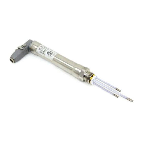
Overall view of the NRG 10-52, NRG 16-52 Fig. 1 Five-pole connector Cover tube Electrode thread Electrode rods Spacer NRG 10-52, NRG 16-52 - USA - Installation & Operating Manual - 850696-00... -
Page 14: Dimensions
Dimensions Thermal insulation provided on site Size 41 1" - 11.5 NPT Fig. 3 NRG 1..-52 with five-pole connector NRG 10-52, NRG 16-52 - USA - Installation & Operating Manual - 850696-00... -
Page 15: Preparing For Installation
Take further measures to protect the equipment from lightning, insects and ■ animals, and salty air. You will need the following tools: Open-ended wrench size 41 ■ Scriber ■ Bolt cutter ■ Flat file ■ NRG 10-52, NRG 16-52 - USA - Installation & Operating Manual - 850696-00... -
Page 16: Installation
Only remove level electrodes that have cooled down. ■ Note An NRG 10-52, 16-52 level electrode can be installed in a single protective tube ■ or level pot [inside diameter 3.94 in(100 mm)] together with a GESTRA level electrode, and a compact level switch or transmitter. If the level limiting elec- trode is installed inside the vessel, it must be at least 1.57 in (40 mm) away from... -
Page 17: Installing The Nrg 10-52, Nrg 16-52, Step 1
Function Length [mm] Function terminal Please enter function! Please enter length! Electrode body Functional ground e.g., MIN alarm e.g., pump off e.g., pump on e.g., MAX alarm NRG 10-52, NRG 16-52 - USA - Installation & Operating Manual - 850696-00... -
Page 18: Installing The Nrg 10-52, Nrg 16-52, Step 2
(The band grounding clamp is available as an optional accessory) Next, measure the resistance again. The value must be < 10 ohms and entered as followed: Measured resistance: __________________________ ohms Boiler wall Visible thread Fig. 4 NRG 10-52, NRG 16-52 - USA - Installation & Operating Manual - 850696-00... -
Page 19: Installation Example With Dimensions
≥ 0.55 in (14 mm) ≤ 90° ∅ 0.8 in (20 mm) Fig. 5 Protective tube (provided on site) if electrode is used as an internal water level limiter NRG 10-52, NRG 16-52 - USA - Installation & Operating Manual - 850696-00... - Page 20 Reducer Pressure relief hole High water HW Low water LW Electrode tip ≥ ≥ Electrode spacing 0.55 in ( 14 mm) (air gap and creepage path) CD Center distance NRG 10-52, NRG 16-52 - USA - Installation & Operating Manual - 850696-00...
-
Page 21: Electrical Connection
Level electrode NRG 10-52, NRG 16-52 Gasket Retaining bracket Ring Lower part of connector Cable gland Contact block Control cable Screw Sealing ring Tools Flat blade screwdriver 3/32 in (2.4 mm) ■ NRG 10-52, NRG 16-52 - USA - Installation & Operating Manual - 850696-00... -
Page 22: Connecting The Level Electrode
Route the connecting cables to the level electrode separately from power lines. ■ Check the connection of the shield to the central grounding point (CGP) in the ■ control cabinet. NRG 10-52, NRG 16-52 - USA - Installation & Operating Manual - 850696-00... - Page 23 Reduce the boiler pressure to 0 psi (0 bar). Allow the level electrode to cool to room temperature. Switch off the supply voltage. Pull out the connector. Then remove the level electrode. NRG 10-52, NRG 16-52 - USA - Installation & Operating Manual - 850696-00...
- Page 24 Fill out the return confirmation (including declaration of decontamination) and send it with the products to GESTRA AG. UL components The level electrode is registered under XACN.E513189. NRG 10-52, NRG 16-52 - USA - Installation & Operating Manual - 850696-00...
- Page 25 For your notes NRG 10-52, NRG 16-52 - USA - Installation & Operating Manual - 850696-00...
- Page 26 For your notes NRG 10-52, NRG 16-52 - USA - Installation & Operating Manual - 850696-00...
- Page 27 For your notes NRG 10-52, NRG 16-52 - USA - Installation & Operating Manual - 850696-00...
- Page 28 You can find our authorized agents around the world at: www.gestra.com GESTRA AG Münchener Straße 77 28215 Bremen Germany Tel. +49 421 3503 0 +49 421 3503 393 e-mail info@de.gestra.com www.gestra.com 850696-00/08-2021cm (809142-00) · GESTRA AG · Bremen...
Need help?
Do you have a question about the NRG 10-52 and is the answer not in the manual?
Questions and answers