
Related Manuals for Bacharach IAM-100


Summary of Contents for Bacharach IAM-100
- Page 1 Integrated Area Monitor and Optional 16-Channel Controller Installation and Operation Manual Instruction 6209-9000 Rev 2 – January 2016 Product Leadership • Training • Service • Reliability...
- Page 2 INSTRUMENT REQUIRE NON-WARRANTY REPAIR, YOU MAY CONTACT THE DISTRIBUTOR FROM WHOM IT WAS PURCHASED OR YOU MAY CONTACT BACHARACH DIRECTLY. IF BACHARACH IS TO DO THE REPAIR WORK, SEND THE INSTRUMENT, PREPAID, TO BACHARACH, INC. AT THE FOLLOWING ADDRESS. 6209-9000 Rev 2...
- Page 3 PROTECTION AND ALL RIGHTS ARE RESERVED. NO PARTY MAY USE OR COPY SUCH SOFTWARE IN ANY MANNER OR FORMAT, EXCEPT TO THE EXTENT THAT BACHARACH GRANTS THEM A LICENSE TO DO SO. IF THIS SOFTWARE IS BEING LOADED ONTO MORE THAN ONE COMPUTER, EXTRA SOFTWARE LICENSES MUST BE PURCHASED.
-
Page 4: Table Of Contents
HOUSING DIMENSIONS ............12 SECTION 4. WIRING INSTRUCTIONS ............15 4.1. Wiring the IAM-100 ................15 4.2. Wiring the IAM-100 Controller .............. 17 4.3. Remote Sensor Head Installation ............19 SECTION 5. OPERATING INSTRUCTIONS ............ 22 5.1. IAM-100 ....................22 5.2. -
Page 5: Overview
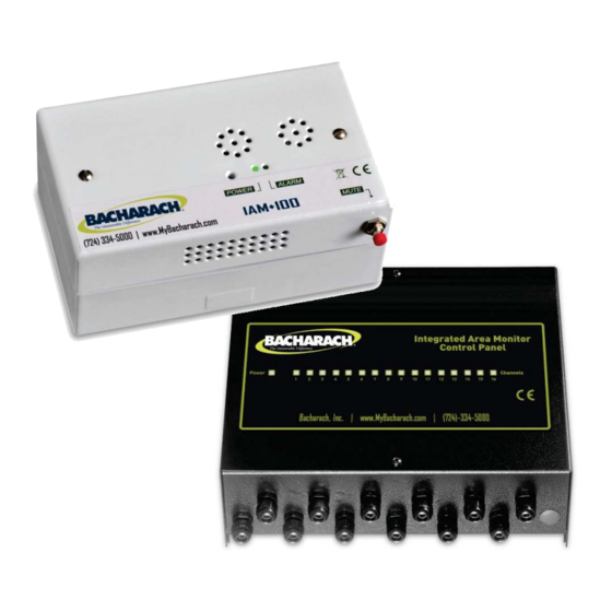
These controllers can be connected to each other enabling the construction of large gas detector systems. 1.2. Applications The IAM-100 is an ideal solution for gas detection in the following occupied spaces: • hotel rooms • storage facilities •... - Page 6 IAM-100 and Controller Manual Figure 1. IAM-100 Figure 2. Optional IAM-100 Controller 6209-9000 Rev 2...
- Page 7 IAM-100 and Controller Manual Figure 3. Sample Architecture Diagram 6209-9000 Rev 2...
-
Page 8: Specifications
IAM-100 and Controller Manual 1.3. Specifications Specification IAM-100 IAM Controller Operating Power 120 VAC/60 Hz or 120 VAC/60 Hz or Supply 220 VAC/50 Hz; 11 W Max 220 VAC/50 Hz; 11 W Max Power Status Green LED Green LED Alarm Status... - Page 9 Calibration Frequency See local regulations (annual test or calibration typical). Semiconductor sensors are non-selective, but calibrated to a specific gas. Bacharach recommends, at a minimum, an annual test of the unit using calibration gas of known concentration. 6209-9000 Rev 2...
-
Page 10: Placing Sensors
The IAM-100 and optional controller (where applicable) should be positioned carefully to avoid mechanical damage (from moving machinery, doors, etc.) and thermal extremes (close to heaters). Units should not be placed unprotected in direct or strong drafts/airflows and areas where water, moisture, or steam is present. -
Page 11: Air Conditioning (Direct Systems Vrf/Vrv)
IAM-100 and Controller Manual 2.2. Air Conditioning (Direct Systems VRF/VRV) To ensure compliance with EN378 at least one detector should be installed in each occupied space being considered. In this case refrigerants are heavier than air and detectors should have their sensors mounted low, e.g., at less than bed height in the case of a hotel or other... -
Page 12: Housing Dimensions
IAM-100 and Controller Manual Section 3. Housing Dimensions Figure 4. Dimensions of the IAM-100 Housing (Front) 6209-9000 Rev 2... - Page 13 IAM-100 and Controller Manual Figure 5. Typical Dimensions of the IAM-100 (Back) 6209-9000 Rev 2...
- Page 14 IAM-100 and Controller Manual Figure 6. Controller Housing 6209-9000 Rev 2...
-
Page 15: Wiring Instructions
IAM-100 and Controller Manual Section 4. Wiring Instructions 4.1. Wiring the IAM-100 Open the IAM-100 by removing the two front cover screws. Remove the metal faceplate and locate the connection terminals. Figure 7. IAM-100 Internal Components 6209-9000 Rev 2... - Page 16 IAM-100 and Controller Manual NOTE: The maximum wire size into terminal blocks is 1.5 mm [16 AWG]. Step Wiring Instructions for the IAM Where applicable, connect the output to the remote IAM Controller at CN6 (see Figure 7) using two-wire cable. This output is not polarity oriented.
-
Page 17: Wiring The Iam-100 Controller
IAM-100 and Controller Manual 4.2. Wiring the IAM-100 Controller Open the IAM-C by removing the two front cover screws. Remove the metal faceplate and locate the connection terminals. To install the IAM-C, refer to the network drawing (Figure 3) and wiring diagram (Figure 8). - Page 18 IAM-100 and Controller Manual Figure 8. Controller Internal Components NOTE: The maximum wire size into terminal blocks is 1.5 mm [16 AWG]. NOTE: Review and agree upon end-user requirements before setting buzzer enable/disable, the relay/buzzer delay and manual vs. automatic reset (latching).
-
Page 19: Remote Sensor Head Installation
It should not be sprayed with cleaning/polishing aerosols. NOTE: For remote sensor configurations, the sensor element is mounted on a small remote sensor PCB that connects to the IAM-100’s main PCB via a 4-wire cable. 6209-9000 Rev 2... - Page 20 Figure 9. Local vs. Remote Sensor Step Instructions Disconnect the cable from the sensor PCB to feed the cable through conduit. Use the IAM-100 enclosure back box knockouts and the remote sensor board back box as needed. 6209-9000 Rev 2...
- Page 21 Step Instructions Immediately refit the connector to the sensor board in the back box. The IAM-100 and its corresponding remote sensor must be kept together as they are calibrated together and are a matched pair. To prevent mix-up, do not remove the sensor boards from a number of units at the same time unless you: •...
-
Page 22: Operating Instructions
IAM-100 and Controller Manual Section 5. Operating Instructions 5.1. IAM-100 Operation Operating Instructions State On power up there is an initial warm-up delay of 5 minutes, during which the green LED will flash at 1 Power Up second intervals. After warm-up, the green LED remains on (constant). -
Page 23: Iam Controller
IAM-100 and Controller Manual Figure 10. Key External Components of the IAM-100 5.2. IAM Controller State Operating Instructions On power up the green LED will flash and will stay on Power Up if there are no faults. If there are faults in any sensor on the system the... - Page 24 IAM-100 and Controller Manual State Operating Instructions Should an alarm occur: • the green LED stays on • the red LED on the relevant channel comes on • the relays operate Errors • the horn operates (can be muted by key switch) •...
-
Page 25: Functional Tests And Calibration
The IAM-100 is calibrated at the factory. After installation, a zero adjustment maybe required due to differences in environmental conditions. IMPORTANT: If the IAM-100 is exposed to a large leak it should be tested to ensure correct functionality, and the sensor replaced if necessary. - Page 26 In applications where life safety is critical, calibration should be done quarterly (every 3 months) or on a more frequent basis. Bacharach is not responsible for setting safety practices and policies. Safe work procedures including calibration policies are best determined by company policy, industry standards, and local codes.
-
Page 27: Bump Testing
(if manual reset has been selected). Before testing the sensors on site the IAM-100 must have been powered up and allowed to stabilize for several hours, preferably over a period of 24 hours. - Page 28 IAM-100 and Controller Manual NOTE: Do not pressurize the sensor. NOTE: You MUST use calibration gas in a balance of air (not N NOTE: Prior to carrying out a bump test, check and adjust the zero setting. Refer to Section 6.3.
-
Page 29: Checking And Setting The Zero Setting
• Screwdriver Step Checking and Setting the Zero Setting Ensure that the IAM-100 is stabilized (on for more than 24 hours) Connect the voltmeter between 0V and VS. Compare the reading of the voltmeter to the factory standby voltage. Adjust P1 as necessary until the voltmeter reading matches the factory standby voltage settings. -
Page 30: Iam Controller
IAM-100 and Controller Manual Figure 13. Checking and Setting the Zero Setting 6.4. IAM Controller If your installation has an IAM Controller, ensure that the controller’s functions are activating accordingly when testing the sensors. Step Checking the IAM Controller Red LED should illuminate for sensors that are in alarm. -
Page 31: Troubleshooting
• The sensor has been damaged or has reached fault) the end of life and needs to be exchanged. Contact Bacharach for instructions and support. • Check the remote cable between the main PCB and the remote sensor PCB to ensure the continuity. -
Page 32: Ce Declaration Of Conformity
IAM-100 and Controller Manual ECLARATION OF ONFORMITY The manufacturer of the Bacharach, Inc. products covered by this 621 Hunt Valley Circle declaration: New Kensington, PA 15068 Year conformity is declared: 2010 Fixed Gas Detector/Transmitter Product(s): IAM-100 Model(s): The undersigned hereby declares that the above referenced products are in conformity with the provisions of the following standard(s) and is in accordance with the following directive(s). - Page 33 IAM-100 and Controller Manual ECLARATION OF ONFORMITY The manufacturer of the products Bacharach, Inc. covered by this declaration: 621 Hunt Valley Circle New Kensington, PA 15068 Year conformity is declared: 2013 Fixed Monitor Controller Product(s): IAM Controller (IAM-C) Model(s): The undersigned hereby declares that the above referenced products are in conformity with the provisions of the following standard(s) and is in accordance with the following directive(s).
- Page 34 IAM-100 and Controller Manual 6209-9000 Rev 2...
- Page 35 IAM-100 and Controller Manual 6209-9000 Rev 2...
- Page 36 IAM-100 and Controller Manual World Headquarters 621 Hunt Valley Circle, New Kensington, Pennsylvania 15068 Phone: 724-334-5000 • Toll Free: 1-800-736-4666 • Fax: 724-334-5001 Website: www.MyBacharach.com • E-mail: help@MyBacharach.com 6209-9000 Rev 2...
Need help?
Do you have a question about the IAM-100 and is the answer not in the manual?
Questions and answers