Vega VEGAPULS 67 Quick Setup Manual
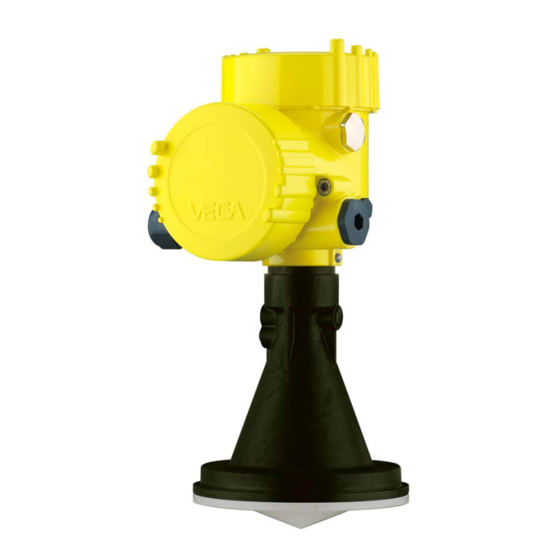
Radar sensor for continuous level measurement of bulk solids, hart and accumulator pack
Hide thumbs
Also See for VEGAPULS 67:
- Operating instructions manual (96 pages) ,
- Quick setup manual (24 pages) ,
- Product information (20 pages)

Subscribe to Our Youtube Channel
Related Manuals for Vega VEGAPULS 67


Summary of Contents for Vega VEGAPULS 67
- Page 1 Quick setup guide Radar sensor for continuous level measurement of bulk solids VEGAPULS 67 HART and accumulator pack Document ID: 47154...
-
Page 2: Table Of Contents
Operating Instructions Manual as well as the Safety Manual that comes with instruments with SIL qualification. These manuals are available on our homepage. Operating instructions VEGAPULS 67 - HART and power pack: Document-ID 40795 Editing status of the quick setup guide: 2021-06-10 VEGAPULS 67 • HART and accumulator pack... -
Page 3: For Your Safety
During work on and with the device, the required personal protective equipment must always be worn. Appropriate use The VEGAPULS 67 is a sensor for continuous level measurement. Due to the integrated accumulator the instrument is particularly suitable as a portable measuring system or test sensor for special applications. -
Page 4: Eu Conformity
This device complies with Part 15 of the FCC Rules. Operation is subject to the following two conditions: • This device may not cause interference, and • This device must accept any interference, including interference that may cause undesired operation of the device This device is approved for unrestricted use only inside closed, sta- tionary vessels made of metal, reinforced fiberglass or concrete. Changes or modifications not expressly approved by the manufac- turer could void the user’s authority to operate this equipment. VEGAPULS 67 • HART and accumulator pack... -
Page 5: Environmental Instructions
That is why we have introduced an environment management system with the goal of continuously improving company environmental pro- tection. The environment management system is certified according to DIN EN ISO 14001. Please help us fulfil this obligation by observing the environmental instructions in this manual: • Chapter " Packaging, transport and storage" • Chapter " Disposal" VEGAPULS 67 • HART and accumulator pack... -
Page 6: Product Description
• Test certificate (PDF) - optional Move to " www.vega.com" and enter in the search field the serial number of your instrument. Alternatively, you can access the data via your smartphone: • Download the VEGA Tools app from the " Apple App Store" or the " Google Play Store" • Scan the DataMatrix code on the type label of the instrument or • Enter the serial number manually in the app... -
Page 7: Mounting
You can find drawings of these mounting options in chapter " Dimen- sions". Fig. 2: Flange mounting of the radar sensor Mounting strap Mounting strap The mounting strap enables simple mounting on the vessel wall or silo top. It is suitable for wall, ceiling or boom mounting. Especially in open vessels this is a very easy and effective way to align the sensor to the bulk solid surface. VEGAPULS 67 • HART and accumulator pack... - Page 8 • Single chamber housing – Angle of inclination 180°, infinitely variable – Angle of inclination in three steps 0°, 90° and 180° • Double chamber housing – Angle of inclination 90°, infinitely variable – Angle of inclination in two steps 0° and 90° Fig. 4: Adjustment of the angle of inclination VEGAPULS 67 • HART and accumulator pack...
-
Page 9: Mounting Instructions
Mounting 1. Distance from the vessel wall > 200 mm 200 mm (7.87") Fig. 6: Distance of the antenna to the vessel wall/socket configuration 2. Keep the nozzle short, round off the nozzle end For further information see chapter " Mounting". VEGAPULS 67 • HART and accumulator pack... -
Page 10: Connecting To Power Supply
9 = sensor is switched on every 24 hours for 3 minutes The green LED characterizes the charging process: • LED flashes = Accumulator is charging • LED lights = accumulator is full, battery charger should be unplugged (accumulator life time) After pressing the key or changing the mode the yellow LED shows the accumulator status for approximately 10 s as follows: • LED lights = accumulator is full • LED flashes = accumulator should be charged VEGAPULS 67 • HART and accumulator pack... - Page 11 4 Connecting to power supply • LED off = accumulator is empty VEGAPULS 67 • HART and accumulator pack...
-
Page 12: Set Up With The Display And Adjustment Module
3. Screw housing lid with inspection window tightly back on Disassembly is carried out in reverse order. The display and adjustment module is powered by the sensor, an ad- ditional connection is not necessary. Fig. 8: Installing the display and adjustment module in the electronics compart- ment of the single chamber housing VEGAPULS 67 • HART and accumulator pack... -
Page 13: Parameter Adjustment
2. Select in the menu item " Medium" the medium of your applica- tion, for example " Gravel/Pebble". 3. Select in the menu item " Application" the vessel, the application and the vessel form, for example, silo. 4. Carry out the adjustment in the menu items " Min. adjustment" and " Max. adjustment". VEGAPULS 67 • HART and accumulator pack... - Page 14 With the adjustment software PACTware and a PC, a high resolution echo curve can be displayed and used to recognize signal changes during operation. In addition, the echo curve of setup can be dis- played in the echo curve window and compared with the current echo curve. Additional settings - False The following circumstances cause interfering reflections and can signal suppression influence the measurement: • High mounting nozzles • Vessel internals such as struts VEGAPULS 67 • HART and accumulator pack...
- Page 15 This is useful if a false signal suppression was carried out with too high a level and not all false signals could be detected. When selecting " Extend", the distance to the medium surface of the created false signal suppression is displayed. This value can now be changed and the false signal suppression can be extended to this range. VEGAPULS 67 • HART and accumulator pack...
-
Page 16: Menu Overview
Backlight Switched on Diagnostics Menu item Parameter Default setting Device status Peak value indi- Distance cator Electronics tem- Temperature perature Measurement re- liability Simulation Percent Curve display Echo curve False signal sup- pression VEGAPULS 67 • HART and accumulator pack... - Page 17 Linear Date/Time Actual date/Actual time Reset HART mode Address 0 Copy instrument settings - Info Menu item Parameter Device name VEGAPULS 6. Instrument version Hardware and software version Date of manufacture Date Instrument features Order-specific characteristics VEGAPULS 67 • HART and accumulator pack...
-
Page 18: Set Up With Smartphone/Tablet, Pc/Notebook Via Bluetooth
The default setting of the sensor PIN is " 0000". First of all you have to change the sensor PIN in the adjustment menu of the sensor, e.g. to " 1111": 1. In the adjustment menu, go to " Additional adjustments", " PIN" Note: The menu item " PIN" is only displayed if in the menu " Setup", " Lock/ Unlock adjustment" the adjustment is released. 2. Change sensor PIN VEGAPULS 67 • HART and accumulator pack... -
Page 19: Connecting
Start the adjustment app and select the function "Setup". The smart- phone/tablet searches automatically for Bluetooth-capable instru- ments in the area. PC/Notebook Start PACTware and the VEGA project assistant. Select the device search via Bluetooth and start the search function. The device auto- matically searches for Bluetooth-capable devices in the vicinity. Connecting The message "... - Page 20 6 Set up with smartphone/tablet, PC/notebook via Bluetooth App view Fig. 12: Example of an app view - Setup sensor adjustment VEGAPULS 67 • HART and accumulator pack...
-
Page 21: Supplement
0 … +45° C (+32 … +167 °F) Ʋ Accumulator operation -20 … +60° C (-4 … +140 °F) Temperature derating accumulator capacity Ʋ +25° C (+77 °F) 100 % Ʋ -10° C (+14 °F) 50 % VEGAPULS 67 • HART and accumulator pack... - Page 22 Notes VEGAPULS 67 • HART and accumulator pack...
- Page 23 Notes VEGAPULS 67 • HART and accumulator pack...
- Page 24 Subject to change without prior notice © VEGA Grieshaber KG, Schiltach/Germany 2021 VEGA Grieshaber KG Am Hohenstein 113 Phone +49 7836 50-0 77761 Schiltach E-mail: info.de@vega.com...
Need help?
Do you have a question about the VEGAPULS 67 and is the answer not in the manual?
Questions and answers