Table of Contents
Advertisement
Quick Links
Advertisement
Table of Contents

Related Manuals for GE CTF878


Summary of Contents for GE CTF878
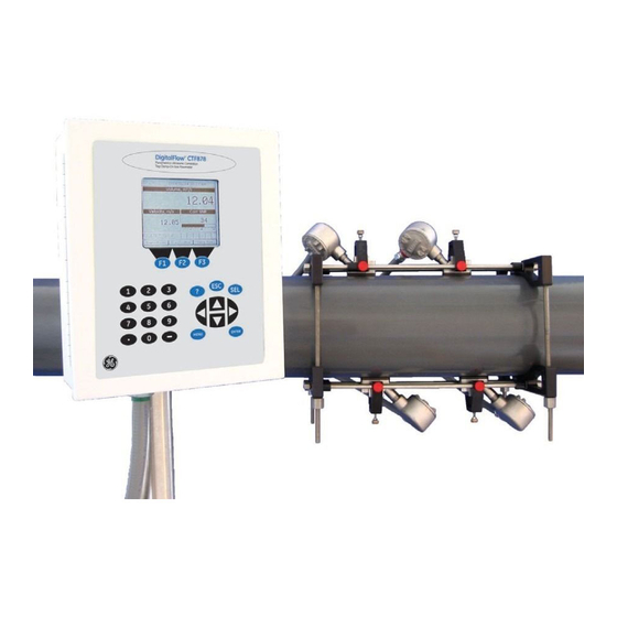
- Page 1 Sensing Model CTF878 Clamp-On Tag Flowmeter User’s Service Manual...
- Page 2 Sensing Model CTF878 Clamp-On Tag Flowmeter User’s Service Manual 910-254SA4 February 2009...
- Page 3 AUTHORIZATION number (RA), and shipping instructions for the return of the instrument to a service center will be provided. 2. If GE instructs you to send your instrument to a service center, it must be shipped prepaid to the authorized repair station indicated in the shipping instructions.
-
Page 4: Table Of Contents
Updating CTF878 Software........ - Page 5 February 2009 Table of Contents (cont.) Chapter 4: Troubleshooting Introduction ..............4-1 Error Code Messages .
- Page 6 Chapter 1...
- Page 7 Diagnostics Introduction........... . 1-1 Entering the Service Menu .
-
Page 8: Introduction
To enter the Service Menu, press the key at the lower right of Menu the CTF878 keypad. The Menu Bar replaces the Status Bar at the top of the screen. Press the [ ] arrow key to scroll from the Site Menu to [ENTER] the Service Menu. -
Page 9: Displaying Diagnostic Parameters
February 2009 Displaying Diagnostic The Diagnostics option enables you to view current diagnostic Parameters parameters without having to open a display window in Operate Mode. To enter the option, scroll to the Diagnostics entry on the [ENTER] Service Menu and press . -
Page 10: Signal Setup
February 2009 Signal Setup The Signal Setup option enables you to set parameters that affect the flowmeter’s signal processing and outputs: • Zero Cutoff • Velocity Averaging • Errors Allowed To enter the option, scroll to the Signal Setup entry on the Service [ENTER] Menu and press . - Page 11 3. The next prompt asks for the Zero Cutoff. Near “zero” flow, the Parameters (cont.) CTF878 may have fluctuating readings due to insufficient flow information. The zero cutoff causes velocity measurements less than the cutoff to be reported as zero. To set the cutoff: a.
-
Page 12: Setting Error Limits
Figure 1-4: Signal Error Limits Option 1. The first prompt asks for the minimum error limit for the correlation signal-to-noise ratio (SNR) calculated by the CTF878. The default value is 10. The E8: SNR error message appears if the SNR falls below the limit programmed here. - Page 13 Use the numeric keys to enter the acceleration limit. c. Press [ENTER] to confirm your entry. Note: In the velocity and acceleration boxes, if the CTF878 currently displays metric measurements, the F1 softkey displays the word “English.” If it displays English [F1] measurements, the F1 softkey displays “Metric.”...
-
Page 14: The Test Option
February 2009 The Test Option Within the Service Menu, the Test option includes three tests to ensure that the CTF878 is performing properly: Test Screen, Test Keys and Watchdog Test. To enter this option, scroll to the Test entry [ENTER] on the Service Menu and press . -
Page 15: Testing The Screen
February 2009 Testing the Screen To test the proper functioning of the CTF878 screen, scroll to the Test [ENTER] Screen option in the Test Menu and press . The screen then shows the message, “Press Any Key To Continue.” Once you press a key, a screen with a checkerboard pattern appears, as in Figure 1-6 below. -
Page 16: Testing The Keys
February 2009 Testing the Keys The Test Keys option checks the functioning of the various keys on the keypad. To start the test, scroll to the Test Keys option on the Test [ENTER] Menu and press . The screen appears similar to Figure 1-7 below. -
Page 17: Testing The Watchdog Timer Circuit
(No) to cancel the test and return to the Menu screen, or [F3] press (Yes) to start the test. The CTF878 should go blank for a few seconds, and then restart. If it does not follow this sequence, consult the factory. - Page 18 Chapter 2...
- Page 19 Updating CTF878 Software........
-
Page 20: Introduction
To enter the Service Menu, press the key at the lower right of Menu the CTF878 keypad. The Menu Bar replaces the Status Bar at the top of the screen. Press the [ ] arrow key to scroll from the Site Menu to [ENTER] the Service Menu. -
Page 21: Resetting To Factory Default Parameters
February 2009 Resetting to Factory For various reasons, you might wish to return the CTF878 to its Default Parameters original settings. The Factory Defaults option enables you to return the meter to its preprogrammed default settings. To enter the option,... -
Page 22: Updating Ctf878 Software
The updating procedure involves three steps: 1. Setting up the CTF878 in Flash Update mode. 2. Selecting the loading interface. 3. Loading the new software from the PC into the CTF878. Caution! To guard against mishap, you should print out, download or otherwise record all logs, settings and other data you wish to save. -
Page 23: Preparation
To prepare the CTF878 for a software update: 1. Disconnect the power to the CTF878. !WARNING! The main power to the CTF878 must be disconnected before proceeding. 2. Open the enclosure, remove the main aluminum shroud and locate the J13 header connector (above the display connector) on the main board (see Figure 2-3 below). -
Page 24: Setting Up The Pc
February 2009 Setting Up the PC 1. From the Start Menu, click Programs/Accessories/Hyperterminal to open the Hyperterminal window. Note: If this is the first time that Hyperterminal has been launched, a Location Information window will pop up (see Figure 2-4 below). - Page 25 February 2009 Setting Up the PC (cont.) 3. A Connect To window appears (see Figure 2-6 below). Under Connect using select the correct communication port. Click OK. Note: COM1 was selected here as an example. Figure 2-6: “Connect To” Window 4.
-
Page 26: Installing New Software
February 2009 Setting Up the PC (cont.) The CTF878 is now connected to the PC. In the lower left-hand corner of the Hyperterminal window it reads “Connected” with the connection duration (see Figure 2-8 below). IMPORTANT: If the proper settings are not made, the CTF878 software update will fail. - Page 27 Installing New Software 2. The meter asks for confirmation. Repeat the options shown in (cont.) Step 1 above. The screens on both the PC and the CTF878 now appear similar to Figure 2-10 below. Figure 2-10: Flash Reloading Window 3. The meter now asks if you wish to reload the flash memory.
- Page 28 February 2009 Installing New Software 5. The “Send File” window appears (see Figure 2-12 below). Select (cont.) the replacement software (designated by a .cod extension) from the folder where it has been stored. Figure 2-12: “Send File” Window 6. From the protocol drop-down menu, select “Xmodem.” The software update now begins as the “Xmodem file send”...
-
Page 29: Completion
(cont.) CTF878 reboots (see Figure 2-14 below). Figure 2-14: Final Window Completion When the transfer is complete, to prepare the CTF878 for operation: 1. Disconnect the power to the CTF878. !WARNING! The main power to the CTF878 must be disconnected before proceeding. - Page 30 Chapter 3...
- Page 31 Calibration Introduction........... . 3-1 Entering the Calibration/Test Menu.
-
Page 32: Introduction
February 2009 Introduction For user convenience, the CTF878 offers a Calibration/Test Menu. This menu enables users to perform a variety of functions that might occasionally be required to calibrate the CTF878. Refer to the Service Menu Map, Figure 3-10 on page 3-11, while moving through the following procedures. -
Page 33: Testing And Calibrating Analog Outputs
February 2009 Testing and Calibrating The Calibration/Test option can be used to test and calibrate the Analog Outputs analog outputs. To enter the option, scroll to the Main Board or to an [ENTER] AnologOut option under the Calibrate / Test Menu and press The screen appears similar to Figure 3-2 below. - Page 34 You have completed calibrating the outputs. To leave the Output window, • [F2] Press (Cancel) to return to Operate Mode without confirming the changes. • [F3] Press (OK) to confirm the new data. The CTF878 returns to Operate Mode. Calibration...
-
Page 35: Testing And Calibrating Analog Inputs
February 2009 Testing and Calibrating The Calibration/Test option can be used to test and calibrate the Analog Inputs analog inputs. To enter the option, scroll to the AnalogIns option [ENTER] under the Calibrate/Test Menu and press . The screen appears similar to Figure 3-2 on page 3-2. -
Page 36: Calibrating Analog Inputs
February 2009 Calibrating Analog Inputs The Analog Input calibration procedure consists of calibrating the analog input zero point (0 or 4 mA) and the full scale point (20 mA). Note: Calibrating analog inputs requires use of a current source. Calibrated analog outputs may be used as a current source. To calibrate an Analog Input, proceed as above, select the desired Calibrate AnalogIn option, and press [ENTER]. -
Page 37: Testing And Calibrating Digital Outputs
• [F3] Press (OK) to confirm the new data. The CTF878 returns to Operate Mode. Repeat the process to calibrate additional Analog Inputs. Testing and Calibrating The Calibration/Test option can be used to test and calibrate (verify Digital Outputs the accuracy of) the digital outputs. -
Page 38: Calibrating (Verifying The Accuracy Of) Digital Outputs
February 2009 Calibrating (verifying the To verify the accuracy of a Digital Output, you must connect a accuracy of) Digital frequency counter to the digital output. Proceeding as above, select Outputs the desired option for the Digital Output to be verified, and press [ENTER]. -
Page 39: Testing And Calibrating Rtd's
They should be very close (within ±1 Hz for frequencies below 1 KHz). You have verified the accuracy of the digital outputs. To leave the Totlizer/Frequency window, press [F3] to exit. The CTF878 returns to Operate Mode. Repeat the process to verify the accuracy of additional Digital Outputs. -
Page 40: Calibrating Rtd's
February 2009 Calibrating RTD’s The RTD calibration procedure consists of setting the low and high temperature readings. To calibrate an RTD you must connect an RTD to the RTD board. Proceeding as above, select the desired Calibrate RTD option, and press [ENTER]. -
Page 41: Testing Eeprom's
(Cancel) to return to Operate Mode without confirming the changes. • [F3] Press (OK) to confirm the new data. The CTF878 returns to Operate Mode. Repeat the process to calibrate additional RTD’s. Testing EEPROM’s To check the EEPROM on each option card, scroll to the Test... - Page 42 February 2009 F3 (accept) or Menu F2 (not accept) Service Site Program Meter Logging Factory Calibrate / Diagnostics Error Limits Test Defaults Test SNR Min Test Screen Velocity Min/Max Acceleration Signal Carrier Min/Max Test Keys DMod Min/Max Reverse Flow? Watchdog Zero Cutoff LP Filter Test...
- Page 43 Chapter 4...
- Page 44 Troubleshooting Introduction........... . 4-1 Error Code Messages.
-
Page 45: Introduction
February 2009 Introduction The CTF878 is a reliable instrument that is easy to maintain. It will provide accurate flow measurement readings as long as it is operated as described in this manual. If problems do arise with the electronics, the pipe, the fluid, or the transducers, the CTF878 displays an error message specifying the possible problem. - Page 46 No error display of another error Measurement is valid. message Receiver Power CTF878 down. Remove shroud. Make sure receiver FPGA not loaded, etc. board is seated correctly and its screws are on tight. Power Board up. Contact factory if problem persists.
-
Page 47: Displaying Diagnostic Parameters
February 2009 Displaying Diagnostic As part of its measurement menu, the CTF878 offers a list of Parameters diagnostic parameters to aid in troubleshooting in the event of flowcell, transducer, or electrical problems. You can select any diagnostic parameter for display as a measurement (see Displaying and Configuring Data, Chapter 2 of the Programming Manual or Chapter 4 of the Startup Guide). -
Page 48: Pipe/Fluid Problems
1. The gas must be homogeneous, single-phase and relatively clean. Although a low level of entrained particles may have little effect on the operation of the CTF878, excessive amounts of solid or liquid particles will absorb or disperse the ultrasound signals. This interference with the ultrasound transmissions through the gas will cause inaccurate flow rate measurements. -
Page 49: Pipe Problems
February 2009 Pipe Problems Pipe-related problems may result either from a failure to observe the installation instructions, as described in the Startup Guide, or from improper programming of the meter. By far, the most common pipe problems are the following: 1. -
Page 50: Transducer Problems
February 2009 Transducer Problems The most common clamp-on transducer problems are listed below: 1. POOR COUPLING TO PIPE Clamp-on transducers must be in intimate contact with the pipe. The pipe wall must be smooth and generally free of paint. The couplant material must fill voids between the transducer and the pipe, and must be firmly bonded to both the pipe and the transducer. - Page 51 Chapter 5...
- Page 52 Parts Replacement Introduction........... . 5-1 Replacing the Fuse.
-
Page 53: Introduction
February 2009 Introduction The electronics console of the CTF878 has been designed to permit easy on-site upgrades and parts replacement. See Figure 5-1 on page 5-9 and Figure 5-2 on page 5-10 for details. The instructions in this chapter, along with a few common tools, are all that is required to perform the following tasks: •... -
Page 54: Replacing The Fuse
February 2009 Replacing the Fuse If it has been determined that the fuse in the CTF878 requires replacement, complete the following steps: !WARNING! The main power to the CTF878 must be disconnected before proceeding. 1. Open the cover on the electronics console. Remove the two mounting screws and lift the clear plastic shroud out of the electronics console. -
Page 55: Removing The Printed Circuit Board
Figure 5-2 on page 5-10 while completing the following tasks: 1. Remove the main power to the electronics console. !WARNING! The main power to the CTF878 must be disconnected before proceeding. 2. Open the electronics console. Remove the two mounting screws and lift the clear plastic shroud out of the electronics console. -
Page 56: Installing An Option Card
A single metal bracket is used to secure all the installed option cards. Note: If the CTF878 presently has no option cards installed, be sure to purchase the metal mounting bracket along with the first option card. -
Page 57: Installing The Printed Circuit Board
8. Reconnect the power line wires to terminal block TB1 on the printed circuit board. Plug all other electrical connectors into the appropriate sockets on the printed circuit board and option cards. See Installation, Chapter 2 of the Startup Guide for instructions on proper wiring of the CTF878. Parts Replacement... - Page 58 1.8 m (6 ft) of the CTF878. Before taking measurements with the CTF878, refer to Initial Setup, Chapter 3 in the Startup Guide, and to Calibration, Chapter 3 in this Service Manual, for instructions on properly setting up the meter for accurate flow rate measurements.
-
Page 59: Replacing The Lcd Display
February 2009 Replacing the LCD The CTF878’s measurements are displayed on a two-pane LCD Display graphic display panel. The LCD display normally provides years of dependable service, but it is easily field-replaceable when necessary. To replace the LCD display, see Figure 5-1 on page 5-9 for the... -
Page 60: Spare Parts
February 2009 Spare Parts All of the necessary components to upgrade or repair the CTF878 flowmeter are readily available from GE Sensing. As a convenient reference, some of the more common spare parts are listed in Table 5-2 below. Table 5-2: Spare Parts List... - Page 61 February 2009 Main Shroud Keypad Cables Main Aluminum Shroud Mounting Screw, 5 pl Display Cable Display Shroud WARNING 1 RCV 2 ARTN DISCONNECT POWER BEFORE 3 TWIND – REMOVING FUSE. 5 RWIND 6 DRTN 7 GATE 8 DRTN 9 ARTN 10 ARTN 11 RI_PK 12 R2_PK...
- Page 62 February 2009 Edging Grommet Option Card Labels to protect cables Shroud Label Main Aluminum Shroud w/ 5 mounting screws Clear Plastic LVD Shroud w/ 2 mounting screws Display Shroud Backlight Cable Standoffs, 7pl Display Cable Keypad Cables Conduit Plate Main PC Board Cable Clamps Option Cards Detail C...
- Page 63 Appendix A...
-
Page 64: Appendix A: Service Record
Service Record Introduction........... . A-1 Data Entry . -
Page 65: Introduction
February 2009 Introduction Whenever any service procedure is performed on the CTF868 flowmeter, the details of the service should be recorded in this appendix. An accurate service history of the meter can prove very helpful in troubleshooting any future problems. Data Entry Record complete and detailed service data for the CTF868 in Table A-1 below. - Page 66 February 2009 Table A-1: Service Record (Continued) Date Description of Service Performed By Service Record...
- Page 67 February 2009 Index Acceleration Limit ..... 1-6 Electronics Console Assembly ..5-9, 5-10 Analog Inputs Electronics, Error Messages .
- Page 68 February 2009 Index (cont.) Parts List, Spare ..... . . 5-8 Test Keys ......1-9 Pipe Test Screen.
- Page 69 Shannon, County Clare Ireland declare under our sole responsibility that the CTF878 Ultrasonic Flowmeter to which this declaration relates, are in conformity with the following standards: • EN 61326:1998, Class A, Annex A, Continuous Unmonitored Operation • EN 61010-1:1993 + A2:1995, Overvoltage Category II, Pollution Degree 2...
- Page 70 Shannon, County Clare Ireland déclarons sous notre propre responsabilité que les CTF878 Ultrasonic Flowmeter rélatif á cette déclaration, sont en conformité avec les documents suivants: • EN 61326:1998, Class A, Annex A, Continuous Unmonitored Operation • EN 61010-1:1993 + A2:1995, Overvoltage Category II, Pollution Degree 2 suivant les régles de la Directive de Compatibilité...
- Page 71 Shannon Industrial Estate Shannon, County Clare Ireland erklären, in alleiniger Verantwortung, daß die Produkte CTF878 Ultrasonic Flowmeter folgende Normen erfüllen: • EN 61326:1998, Class A, Annex A, Continuous Unmonitored Operation • EN 61010-1:1993 + A2:1995, Overvoltage Category II, Pollution Degree 2 gemäß...
- Page 72 1100 Technology Park Drive Billerica, MA 01821-4111 Web: www.gesensing.com Ireland Sensing House Shannon Free Zone East Shannon, Co. Clare Ireland...
Need help?
Do you have a question about the CTF878 and is the answer not in the manual?
Questions and answers