
Summary of Contents for L&T Electrical & Automation 1 Phase DIN Rail Meter
- Page 1 1 Phase DIN Rail Meter USER MANUAL FOR 1 PHASE DIN RAIL METER Doc.No.4D060 Rev.0 L&T Electrical & Automation...
-
Page 2: Features & Technical Specifications
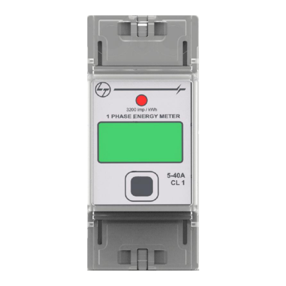
FEATURES & TECHNICAL SPECIFICATIONS FEATURES Terminal sealing provision Terminal cover Display Pulse LED Optical communication Push button Terminal sealing provision LCD display Push-to-Push consumption, Daily, Weekly, Monthly consumption. Terminal covers to avoid direct contact of the supply terminals along with sealing provision. ... -
Page 3: Wiring Diagram
WIRING DIAGRAM, OPERATING INSTRUCTIONS & DISPLAY WIRING DIAGRAM Neutral Phase 1 Phase Load OPERATING INSTRUCTIONS Parameter scrolling: The default display mode is Auto Scroll Mode in which the parameters scroll automatically. On pressing key, the meter display goes to manual mode. If key press doesn’t happen for approximately 30 seconds, meter display returns to default mode i.e. -
Page 4: Display Explanation
DISPLAY PARAMETERS Table 1. DISPLAY EXPLANATION Sl. No. Parameter Display Legend Quantities measured Energy, Voltage, Amps, Power kWh, V, A, kW Different consumptions Present day D (Flashing) Present week W (Flashing) Present month M (Flashing) Previous day Previous week Previous month Push-to-Push kWh consumption(present) T (Flashing) Push-to-Push kWh consumption(previous) - Page 5 DISPLAY PARAMETERS & METER SETTING Parameter LCD Pattern Parameter LCD Pattern Meter Mode of communication Byte of IP Address of Configuration Wi-Fi Module * display Byte of IP Byte of IP Address of Address of Wi-Fi Wi-Fi Module * Module * Byte of IP Meter Modbus Address of Wi-Fi...
- Page 6 METER SETTING & MEMORY MAP Memory Map Table 3. Address Parameters Words Read only Parameters ( Function Code 4) Instantaneous Parameters 30001 R Phase Voltage 0.01 30007 R Phase Current 0.001 30013 Average Voltage 0.01 30015 Average Current 0.001 30017 Total Active Power 0.0001 30023...
- Page 7 DIMENSIONS All dimensions are in mm INSTALLATION PROCEDURE STEP 1 STEP 3 STEP 4 STEP 2 PRESS PULL** * For terminal cover sealing, wire used should be of maximum 0.8mm diameter. UN-INSTALLATION PROCEDURE Note: 1) Before installing & uninstalling the meter make sure that the Power supply to meter is switched off.
-
Page 8: Warranty And Disclaimer
WARRANTY & DISCLAIMER WARRANTY Larsen & Toubro warrants that 1 PHASE DIN RAIL ENERGY METER is free from defects in workmanship and material. Larsen & Toubro’s obligation under this warranty shall be for a period of 18 months from the date of sale subject to the following terms and conditions provided the notice of defects and satisfactory proof thereof is given to Larsen &... - Page 9 3 Phase DIN Rail Meter USER MANUAL 3 PHASE DIN RAIL ENERGY METER L&T Electrical & Automation Doc.No.4D060 Rev.0...
-
Page 10: Technical Specifications
FEATURES Sealing provision Terminal Display cover Pulse rate Optical communication Push button Bright LCD display Push to Push consumption Terminal covers to avoid direct contact of the supply terminals along with sealing provision. * Data transfer through “Wi-Fi” and “MODBUS”. ... -
Page 11: Connection Diagram
CONNECTION DIAGRAM R-Phase Y-Phase 3 Phase B-Phase supply Neutral LOAD OPERATING INSTRUCTIONS Parameter scrolling: Manual Scroll: Press and release the push button to view the next parameter. Meter will continue to be in Manual scroll mode once push button is pressed and will change over to Auto scroll mode if the Push button is left inactive for 5 minutes. -
Page 12: Display Parameters
DISPLAY DISPLAY EXPLANATION Sl # Parameter Display Legend Value of quantity measure Units of Energy, Voltage, Current and kWh, V, A, kW Power Maximum demand Presence of R, Y and B phase voltages and blinks when current flows to the load. - Page 13 Current reading R phase Current reading Y phase Current reading B phase Frequency Power factor Instantaneous Active Power Instantaneous Reactive Power Instantaneous Apparent Power Present month Demand Previous month Demand Cumulative energy (kWh) Present Push to push consumption Push to Push consumption Present day consumption (kWh) Previous day consumption (kWh) Present week consumption (kWh)
-
Page 14: Configuring Communication
Previous month consumption (kWh) First byte of IP address * Second byte of IP address * Third byte of IP address * Fourth byte of IP address * Slave ID ** Baud rate ** Parity ** Config Indicates change over from manual scroll mode to auto scroll mode Indicates data collection... -
Page 15: Un-Installation Procedure
DIMENSION All dimensions are in mm INSTALLATION PROCEDURE STEP 1. STEP 2. STEP 3. STEP 4. PRESS PRESS PULL PULL * For terminal cover sealing, wire used should be of maximum 0.8mm diameter Warning: Terminal cover has to be used for operator protection. As soon as the connections are made the terminals has to be covered by terminal cover. -
Page 16: Warranty
WARRANTY Larsen & Toubro warrants that 3 PHASE DIN RAIL ENERGY METER is free from defects in workmanship and material. Larsen & Toubro obligation under this warranty shall be for a period of 18 months from the date of sale subject to the following terms and conditions provided the notice of defects and satisfactory proof thereof is given to Larsen &... - Page 17 RS485 Module DIN Energy Meter Module DIN Energy Meter USER MANUAL DIN RS485 MODULE Module DIN Energy Meter WiFi Module DIN Energy Meter L&T Electrical & Automation Doc.No.4D060 Rev.0...
-
Page 18: Specifications
FEATURES Terminal sealing provision Terminal cover Optical communication Power on RS485 connector DIN RS485 module is used to collect data from L&T make DIN meters through optical interface and to make it available for the user through RS485 port and modbus protocol. This RS485 module is compatible with 1 Phase as well as 3 Phase meters. -
Page 19: Interface Details
CONNECTION DIAGRAM Neutral Phase Modbus interface STANDARDS APPLICABLE Radiated RF field immunity : IEC 61000-4-3 Conducted RF immunity : IEC 61000-4-6 Conducted RF emissions : CISPR 22 Radiated RF Emission : CISPR-22-A Fast transient burst (2kV) : IEC 61000-4-4 ... -
Page 20: Memory Map
MEMORY MAP Address Parameters Words (if no specific format is mentioned, format is HEX) Read only Parameters ( Supported by Function Code 4) Instantaneous Parameters 30001 R Phase Voltage 0.01 30003 Y Phase Voltage 0.01 30005 B Phase Voltage 0.01 30007 R Phase Current 0.001... - Page 21 LS DATA -Last 4 IP kWh 30049 1st Integration period -kWh 0.01 30051 2nd Integration period (Previous of 1 integration period )-kWh 0.01 30053 3rd Integration period (Previous of 2nd integration period )-kWh 0.01 30055 4th Integration period (Previous of 3rd integration period)_kWh 0.01 Meter Serial Number 30057...
- Page 22 DIMENSION All dimensions are in mm Page 6 of 8...
- Page 23 INSTALLATION PROCEDURE RS485 module should be connected to the left side of the DIN meter (as per the picture shown in un-installation procedure) as it communicates with meter through optical port. PULL PRESS UN-INSTALLATION PROCEDURE PULL PULL PULL CAUTION!!!: 1) Before installing, uninstalling, connecting the RS485 connector to the module and disconnecting the RS485 connector from the module make sure that the Power supply to the module is switched off.
- Page 24 WARRANTY Larsen & Toubro warrants that the RS485s module is free from defects in workmanship and material. Larsen & Toubro obligation under this warranty shall be for a period of 18 months from the date of sale subject to the following terms and conditions provided the notice of defects and satisfactory proof thereof is given to Larsen &...
- Page 25 ™ WiFi Module DIN Energy Meter USER MANUAL WiFi MODULE L&T Electrical & Automation Doc.No.4D060 Rev.0...
- Page 26 FEATURES Terminal sealing provision Terminal cover Optical communication Reset Key Power on Mode Key Wi-Fi is one of the most popular wireless communication standards on the market. WiFi module is used to collect data from L&T make DIN meters through optical interface and to make it available for the user through WiFi network.
- Page 27 Mode key helps to configure the WiFi module to infrastructure or ad-hoc mode by pressing it for 1 second .If the same key is pressed for more than 10sec then the module will be configured to factory defaults. Reset Key resets the module. Power ON LED gives the indication of the selected mode.
-
Page 28: First Time Installation
STANDARDS APPLICABLE Radiated RF field immunity : IEC 61000-4-3 Conducted RF immunity : IEC 61000-4-6 Conducted RF emissions : CISPR 22 Radiated RF Emission : CISPR-22-A Fast transient burst (2kV) : IEC 61000-4-4 Electrostatic Discharge (±15kV): IEC 61000-4-2 ... - Page 29 Ad-hoc: Ad-hoc is another mode of connectivity available in Wi-Fi. By using this mode, devices are capable for communicating directly each other. All devices are connected in peer to peer communication mode without using any Access point (router/switch) between devices. Note that android OS does not support ad-hoc mode communication.
- Page 30 DIMENSIONS All dimensions are in mm Page 6 of 8...
- Page 31 INSTALLATION PROCEDURE Wi-Fi module should be connected to the left side of the DIN meter (As per the picture shown in un-installation procedure) as it communicates with meter through optical port. PULL PRESS UN-INSTALLATION PROCEDURE PULL PULL PULL Note: 1) Before installing & uninstalling the meter make sure that the Power supply to the meter is switched off.
- Page 32 WARRANTY Larsen & Toubro warrants that the Wi-Fi module is free from defects in workmanship and material. Larsen & Toubro obligation under this warranty shall be for a period of 1 year from the date of sale subject to the following terms and conditions provided the notice of defects and satisfactory proof thereof is given to Larsen &...
Need help?
Do you have a question about the 1 Phase DIN Rail Meter and is the answer not in the manual?
Questions and answers