
Related Manuals for Samson 3375-10


Summary of Contents for Samson 3375-10
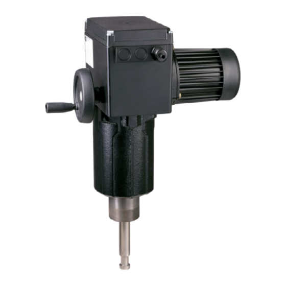
- Page 1 EB 8332-1 EN Translation of original instructions Type 3375 Electric Actuator Three-step version Edition August 2016...
- Page 2 Note on these mounting and operating instructions These mounting and operating instructions assist you in mounting and operating the device safely. The instructions are binding for handling SAMSON devices. The images shown in these instructions are for illustration purposes only. The actual product may vary.
-
Page 3: Table Of Contents
Contents Safety instructions and measures ..............1-1 Notes on possible severe personal injury ............1-4 Notes on possible personal injury ..............1-5 Notes on possible property damage .............1-6 Markings on the device ................2-1 Nameplate ....................2-1 Design and principle of operation ...............3-1 Fail-safe action ...................3-1 Additional equipment ..................3-2 Technical data ....................3-3 Dimensions in mm ..................3-5... - Page 4 Contents Removal ....................11-1 Repairs ....................12-1 12.1 Returning the actuator to SAMSON ............12-1 Disposal ....................13-1 Certificates ....................14-1 Annex......................15-1 15.1 Parts for retrofitting and accessories ............15-1 15.2 After-sales service ..................15-2 EB 8332-1 EN...
-
Page 5: Safety Instructions And Measures
In case operators intend to use the actuator in other applications or conditions than specified, contact SAMSON. SAMSON does not assume any liability for damage resulting from the failure to use the de- vice for its intended purpose or for damage caused by external forces or any other external factors. - Page 6 Î Check with the plant operator for details on further protective equipment. Revisions and other modifications Revisions, conversions or other modifications of the product are not authorized by SAMSON. They are performed at the user's own risk and may lead to safety hazards, for example. Fur- thermore, the product may no longer meet the requirements for its intended use.
- Page 7 Î For wiring, maintenance and repair, observe the relevant safety regulations. Referenced documentation The following documents apply in addition to these mounting and operating instructions: − Mounting and operating instructions of the valve on which the electric actuator is mount- ed, e.g. for SAMSON valves: u EB 5861 for Type 3260 Three-way Valve u EB 5868-1 for Type 3214 Globe Valve balanced by a diaphragm u EB 8012 for Type 3241 Globe Valve, ANSI and JIS version u EB 8015 for Type 3241 Globe Valve, DIN version...
-
Page 8: Notes On Possible Severe Personal Injury
Safety instructions and measures 1.1 Notes on possible severe personal injury DANGER Risk of fatal injury due to electric shock. Î Before connecting wiring, performing any work on the device or opening the de- vice, disconnect the supply voltage and protect it against unintentional reconnec- tion. Î Only use power interruption devices that can be protected against unintentional re- connection of the power supply. -
Page 9: Notes On Possible Personal Injury
Safety instructions and measures 1.2 Notes on possible personal injury WARNING Crush hazard arising from moving parts. The form-fit version of the electric actuator contains moving parts (actuator and plug stems), which can injure hands or fingers if inserted into the actuator. Î Do not insert hands or finger into the yoke while the valve is in operation. Î Disconnect the supply voltage and protect it against unintentional reconnection be- fore performing any work on the control valve. Î... -
Page 10: Notes On Possible Property Damage
Safety instructions and measures 1.3 Notes on possible property damage NOTICE Risk of damage to the electric actuator due to the supply voltage exceeding the per- missible tolerances. The Type 3375 Electric Actuator is designed for use according to regulations for low-voltage installations. Î Observe the permissible tolerances of the supply voltage. Risk of actuator damage due to excessively high tightening torques. -
Page 11: Markings On The Device
2 Markings on the device 2.1 Nameplate SAMSON 3375-21 Electric Actuator Var.-ID 0000000.00 Serial no. 0000 *000000* 0062 SAMSON AG, Germany Made in Germany 1 Type 2 Configuration ID 3 Serial number 4 Supply voltage; power line frequency 5 Power consumption 6 Rated travel 7 Stroking speed... - Page 12 EB 8332-1 EN...
-
Page 13: Design And Principle Of Operation
The actuator is a linear actuator which is controlled by a three-step signal. Depending on the version with or without fail-safe ac- tion, it is particularly suitable for mounting on SAMSON Series 240 and 250 Valves as well as to Type 3214 Valve (DN 300 and 400). Principle of operation The electric actuator consists of a reversible asynchronous motor and a maintenance-free planetary gear with ball screw drive. -
Page 14: Additional Equipment
Design and principle of operation 3.2 Additional equipment Mechanical limit contacts Optionally, the actuator can be equipped with two limit contacts. They consist of two changeover switches. Their switching posi- tions are changed independently from one another by continuously adjustable cam disks. -
Page 15: Technical Data
Design and principle of operation 3.3 Technical data Table 3-1: Technical data Type 3375 Type 3375 Actuator stem Actuator stem Fail-safe action Without extends retracts Connection (form-fit) M30x1.5 M60x1.5 M30x1.5 M60x1.5 M30x1.5 M30x1.5 M60x1.5 Rated travel At 50 Hz Stroking speed in At 60 Hz mm/s In the event of fail- –... - Page 16 Design and principle of operation Type 3375 Conformity Materials Bottom section Spheroidal graphite iron Middle section Cast aluminum alloy Housing Motor housing Cast aluminum alloy Fan guard Plastic Cover Glass-fiber-reinforced plastic Actuator stem Stainless steel Weight kg (approx.) 11.7 14.5 19.5 22.5 Additional equipment Limit contacts Two adjustable limit contacts with changeover switches;...
-
Page 17: Dimensions In Mm
Design and principle of operation 3.4 Dimensions in mm Connection Ød Fig. 3-3: Dimensions for Type 3375 Table 3-2: Dimensions Type 3375 Connection M30x1.5 M60x1.5 M30x1.5 M60x1.5 M30x1.5 M30x1.5 M60x1.5 Rated travel (mm) Actuator stem Ød in mm H1 stem retracted (mm) H1 stem extended (mm) (mm) EB 8332-1 EN... - Page 18 EB 8332-1 EN...
-
Page 19: Shipment And On-Site Transport
Î Observe the storage instructions. 4.2 Removing the packaging Î Avoid long storage times. from the actuator Î Contact SAMSON in case of different storage conditions or longer storage times. Note Do not remove the packaging until immedi- ately before mounting and start-up. - Page 20 Shipment and on-site transport Storage instructions − Protect the electric actuator against exter- nal influences (e.g. impact). − Protect the electric actuator against mois- ture and dirt. − Make sure that the ambient air is free of acids or other corrosive media. − Observe the permissible storage tem- perature from –20 to +70 °C.
-
Page 21: Installation
Installation 5 Installation 5.1 Installation conditions Work position If not described otherwise in the valve documentation, the work position for the control valve is the front view looking onto the operating controls. Mounting orientation The control valve can be installed in the pipeline in any desired position. However, a sus- pended mounting position of the actuator is not permissible (see Fig. 5-1). 0...90° 0...90° Fig. 5-1: Mounting position EB 8332-1 EN... -
Page 22: Preparation For Installation
Installation 5.2 Preparation for installation Before mounting, make sure the following conditions are met: − The actuator is not damaged. Proceed as follows: Lay out the necessary material and tools to have them ready during installation work. Handwheel Cover screws Phillips screws are used to fasten the actua- Fig. 5-2: Manual override tor housing cover. -
Page 23: Installing The Control Valve Into The Pipeline
Installation 5.5 Installing additional equip- ment DANGER Risk of fatal injury due to electric shock. Î Before installing electrical accessories, switch off the supply voltage and discon- nect the signal line. 5.5.1 Retrofitting limit contacts To install the limit contacts, the following ret- rofit kits are required: −... - Page 24 Installation 9 (2x) 16 (2x) Serrated ring Spacer Snap ring 18 (2x) 19 (2x) 16 Screw for adjustment gear 17 Terminal board 18 Adjustment gear 19 Contact cam 20 Cam holder Not required for Type 3375 Fig. 5-4: Mechanical limit contacts Note The contact cams (19) are ready-mounted to the cam holder (20) and the retaining rings (9) to form the contact cam unit (21, see Fig. 5-6 on page 5-7).
- Page 25 Fig. 5-5: Basic unit Note − The listed retrofit kits also contain parts needed to retrofit other SAMSON actuators. Not all the parts in the kits are required for the Type 3375 Actuator. − To undo the screws on the housing cover,...
- Page 26 Installation Actuators without resistance transmitters Fig. 5-8. Make sure that the outermost cog of the contact cam unit engages in the gearwheel of the intermediate gear Note (1). In addition, the adjustment gears Parts from the basic unit and the retrofit kit (18) must engage properly in the corre- (see Fig. 5-4 and Fig. 5-5) are required.
- Page 27 Installation 11.1 11.2 Fig. 5-6: Inside view · Actuator without resistance transmitters When actuator stem When actuator stem retracted: extended: Actuator stem Retracted Extended Fig. 5-7: Contact cams and cam holder Fig. 5-8: Contact cam unit Intermediate gear Bearing sleeve Spindle gear Terminal board Serrated ring Adjustment gear 11.1...
-
Page 28: Installing The Resistance Transmitters
Installation Actuators with resistance transmitters Actuators without limit contacts 1. Unscrew fastening screws. Slide the actu- Note ator board (12) from its guiding. Slightly Parts from the retrofit kit (see Fig. 5-5 on lift the board and continue pushing it fur- page 5-5) are required. - Page 29 Installation 11.1 Actuator board (top view): 11.1 Intermediate gear Spindle gear Serrated ring 11.1 Spindle 1 Actuator board Bearing sleeve Gear for potentiometer 1 Gear for potentiometer 2 Fig. 5-9: Inside view · Actuator without limit contacts EB 8332-1 EN...
- Page 30 Installation Actuators with limit contacts lift the board and continue pushing it fur- ther towards the cable entry. 1. Unscrew screws on housing cover and 4. Slide new actuator board into its guid- take the cover off the actuator. ing. Make sure that all the gears are 2.
-
Page 31: Electrical Connection
Installation 5.6 Electrical connection DANGER Risk of fatal injury due to electric shock. Î Upon installation of the electric cables, you are required to observe the regula- tions concerning low-voltage installations according to DIN VDE 0100 as well as the regulations of your local power sup- plier. - Page 32 Installation Type 3375 Actuator > eL: Actuator stem retracts – aL: Actuator stem extends e53: Stem retracted in end position a43: Stem extended in end position Controller Mechanical limit contacts Resistance transmitters 81 82 83 91 92 93 41 44 42 51 54 Fig. 5-11: E lectrical connection Table 5-1: Cables and stranded wires that can be used Cable...
-
Page 33: Start-Up
Start-up 6 Start-up 3. Use the motor or manual override to move the actuator stem to the point at Once the actuator has been mounted cor- which the contact should react. rectly and the wiring has been performed as 4. Use a hex screwdriver to turn the spindle described in the 'Installation' section, the of the adjustment gears (18) for the up- electric actuator is ready for use and can be... -
Page 34: Adjusting The Resistance Transmitter
Start-up 6.2 Adjusting the resistance Zero adjustment transmitter 1. Use the motor or manual override to move the actuator stem to the desired The gears of the resistance transmitters (22) end position. and (23) must be put onto their shafts to cor- 2. -
Page 35: Operation
Operation 7 Operation 7.2 Manual override The handwheel (1 in Fig. 7-2) is used for 7.1 Three-step mode manual override. Turn the handwheel clock- wise to move the actuator in 'aL' direction In three-step mode, the actuator stem is and counterclockwise to move it in the 'eL' moved in the corresponding direction by ap- direction (see Fig. 7-1). - Page 36 EB 8332-1 EN...
-
Page 37: Malfunctions
Malfunctions 8 Malfunctions Î Troubleshooting (see Table 8-1) Note Contact SAMSON's After-sales Service for malfunctions not listed in the table. Table 8-1: Troubleshooting Error Possible reasons Recommended action Actuator stem does not move. Actuator is blocked. Î Check attachment. Î Remove the blockage. - Page 38 EB 8332-1 EN...
-
Page 39: Servicing
Servicing 9 Servicing Note The electric actuator was checked by SAMSON before it left the factory. − The product warranty becomes void if service or repair work not described in these instructions is performed without prior agreement by SAMSON's After-sales Service. - Page 40 EB 8332-1 EN...
-
Page 41: Decommissioning
Decommissioning 10 Decommissioning Decommissioning To decommission the electric actuator for repair work or disassembly, proceed as DANGER follows: Risk of fatal injury due to electric shock. Î Put the control valve out of operation. Î Before disconnecting live wires, switch See associated valve documentation. - Page 42 10-2 EB 8332-1 EN...
-
Page 43: Removal
Removal 11 Removal 2. Retract actuator stem as described in the 'Operation' section. 3. Undo the stem connector parts between DANGER the plug and actuator stems. Risk of fatal injury due to electric shock. 4. Unscrew the ring nut on the valve bon- Î... - Page 44 Î Use suitable lifting equipment. 11-2 EB 8332-1 EN...
-
Page 45: Repairs
Risk of actuator damage due to incorrect service or repair work. Î Do not perform any repair work on your own. Î Contact SAMSON's After-sales Service for repair work. 12.1 Returning the actuator to SAMSON Defective actuators can be returned to SAMSON for repair. - Page 46 12-2 EB 8332-1 EN...
-
Page 47: Disposal
Disposal 13 Disposal We are registered with the German national register for waste electric equipment (stiftung ear) as a producer of electrical and electronic equipment, WEEE reg. no.: DE 62194439 Î Observe local, national and internation- al refuse regulations. Î Do not dispose of components, lubricants and hazardous substances together with your other household waste. - Page 48 13-2 EB 8332-1 EN...
-
Page 49: Certificates
Certificates 14 Certificates The following certificate is shown on the next page: − EU declaration of conformity The certificate shown was up to date at the time of publishing. The latest certificate can be found on our website at: u www.samsongroup.com > Products & Applications > Product selector > Actuators > 3375 EB 8332-1 EN 14-1... - Page 50 Certificates EU declaration of conformity 14-2 EB 8332-1 EN...
-
Page 51: Annex
Annex 15 Annex 15.1 Parts for retrofitting and accessories Parts for retrofitting Basic unit for limit contacts and/or resistance transmitters Order no. 1400-8829 Mechanical limit contacts Order no. 1402-0898 Resistance transmitter On request Gear wheel for resistance transmitter PCB Order no. 1992-5885 Accessories Set with three cable glands M20x1.5 with metal nut (SW 23/24) Order no. 1400-8828 EB 8332-1 EN 15-1... -
Page 52: After-Sales Service
E-mail contact You can reach our after-sales service at u aftersalesservice@samsongroup.com. Addresses of SAMSON AG and its subsid- iaries The addresses of SAMSON, its subsidiaries, representatives and service facilities worldwide can be found on our website (u www.samsongroup.com) or in all SAMSON product catalogs. Required specifications Please submit the following details: −... - Page 56 EB 8332-1 EN SAMSON AKTIENGESELLSCHAFT Weismüllerstraße 3 · 60314 Frankfurt am Main, Germany Phone: +49 69 4009-0 · Fax: +49 69 4009-1507 samson@samsongroup.com · www.samsongroup.com...
Need help?
Do you have a question about the 3375-10 and is the answer not in the manual?
Questions and answers