
Related Manuals for GAI-Tronics Help Point PHP400 GSM


Summary of Contents for GAI-Tronics Help Point PHP400 GSM
- Page 1 Installation and User Guide PHP400 GSM Help Point With Ampetronic HLS-DM2 Induction Loop Amplifier 230V AC power supply GAI-TRONICS A division of Hubbell Ltd. Doc. No. 502-20-0130-015 Iss 1. Apr 2019. (CN42260-008)
-
Page 2: Table Of Contents
CONTENTS Safety and Care Information ..................4 Product Description and Features ................5 Operation / Testing ....................7 3.1. Making a Call ....................7 3.2. Answering calls ..................... 7 3.3. Ending the Call ..................... 7 3.4. Receiving calls ....................7 3.5. - Page 3 7.3. ERROR light flashing Long/Fast ..............28 7.4. FUNCTION and ERROR lights flashing Long/Fast ........28 7.5. FUNCTION and ERROR lights flashing Short/Slow ........28 Induction Loop Amplifier ..................29 Cleaning ......................... 29 9.1. Normal Cleaning ..................29 9.2. Stainless Steel Push-buttons ..............29 9.3.
-
Page 4: Safety And Care Information
Safety and Care Information ▲ Please read these instructions thoroughly before starting installation. These products must only be installed and maintained by competent personnel familiar with electrical and telephone installation. ▲ IMPORTANT: THIS EQUIPMENT CONTAINS HAZARDOUS VOLTAGES ▲ THIS EQUIPMENT MUST BE EARTHED ▲... -
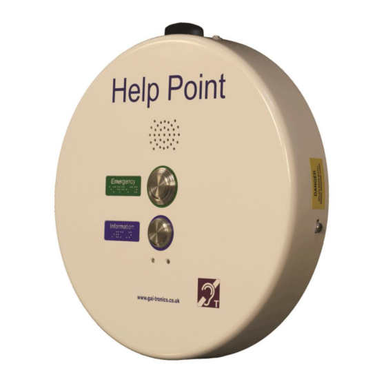
Page 5: Product Description And Features
The fitted aerial is rugged but has limited resistance to deliberate damage or vandalism. The aerial can be mounted remotely if appropriate, see section 4.7 Product Description and Features This manual describes the GSM (cellular) version of the GAI-Tronics 400mm circular Help Point, with features including: •... - Page 6 The Help Point casing is a two-part construction with electronics in both sections. The 2 sections are held together with 4 security screws though the sides, and there are several cables between the 2 sections. Cable entry points are provided to top and bottom of the casing.
-
Page 7: Operation / Testing
Operation / Testing Making a Call 3.1. To make a call, press the required button and wait for connection. A brief burst of tones is heard to signify that the call has been placed to the pre-programmed number. Answering calls 3.2. -
Page 8: Installation And Dimensions
• Charger status (should say “on”) • Battery voltage (normally 0V) • Temperature (now, min & max) Note that min and max will show 127 or 128 on first reading after power up. • IMEI (the IMEI number of the GSM module) •... -
Page 9: Site Requirements
4.4. • Qualified personnel only Installation and maintenance must only be carried out by appropriately qualified and trained personnel. Contact GAI-Tronics if installation service is required. • Mains supply Mains connection must be made via a 2 pole disconnection device, with a minimum contact clearance of 3mm in accordance with EN 62368-1 Annex L. -
Page 10: Installation Method
Take care when separating the 2 sections – there are 4 cable sets between the 2 halves: 1. Induction loop audio (2 conductors) 2. DC power (2 conductors) 3. Earth cable 4. Antenna cable. These cables are deliberately short, but will allow the front section to sit to the left of the rear for set-up purposes if required. -
Page 11: Connections & Set-Up
GAI-Tronics can provide a 2.5m mounting pole that can support the Help Point and position the aerial at height, to improve reception and make it less vulnerable. Please contact GAI-Tronics for details. Connections & Set-up Connections between Front and Rear Sections 5.1. -
Page 12: Internal Power Connections
As an option, the PHP400 GSM can be equipped with up to 2 external relay outputs, controlled by the telephone software. Contact GAI-Tronics for details. The additional outputs are provided on terminal blocks TB1 & TB2 below the main PCB. -
Page 13: Installing The Sim
Note that connections differ slightly dependant on whether relays are fitted or not. Installing the SIM 5.7. IMPORTANT: before installing or changing a SIM card, always make sure that the telephone is powered down by ensuring that the DC power source cable is disconnected from the main PCB. -
Page 14: Switch On And Test
FUNCTION ERROR Meaning Long/fast Incoming call. Call in progress. SIM card is locked, PIN code Long/Fast required. * SIM card is blocked, PUK code Long/fast Long/Fast required. * Short/slow Short/slow Weak signal. Insufficient power to operate, but Short/slow charging. Fault, such as no SIM. Momentary indication to acknowledge a press of the On/Off button... -
Page 15: Switching The Phone Off (Power Down)
5. Fit the faceplate: a. Carefully place the front section over the rear section, taking care not to trap any cables. b. Insert the 4 fixing screws and tighten. c. Check that a good weatherproof seal exists between the front and rear sections. -
Page 16: Sending Commands By Sms
NOTE the PIN code referred to in this manual is a security code specifically for programming the GAI-Tronics GSM telephone via SMS commands – it is not a lock code and is not related to the SIM card. It is not required for making or receiving calls. -
Page 17: List Of Commands (For Use With Either Sms Or Usb)
Example 2: AT!CFG5=1<cr> sets the phone to inhibit incoming calls. Notes for USB commands • The AT! Commands are specific to this product range and are not related to the Hayes™ AT command set • Commands may be concatenated by entering a semicolon delimiter, for example AT!CFG5=1;STAT<cr>... - Page 18 STAT1 for information about faults: Hook: On/Off Power break: No/Yes Loop: Pass/Fail Acoustic loop: Pass/Fail Keyboard: Pass/x stuck on Battery: OK/Fault Explanation of stat1 fault results: Hook: Reserved for handset phones (not applicable to Help Points). Will always report “On” for a Help Point. Power break: No = normal, Yes = power has been interrupted Loop: Pass = normal, Fail = the handset integrity loop is broken, meaning that the handset has been detached or vandalised...
- Page 19 Mode: GSM/GPRS/EDGE/WCDMA/HSDPA/HSUPA/HSPA Signal: -89dBm Avg battery current When Idle: 10mA During Call: 200mA STAT4 Environmental information: Temperatures Transmitter Now: 25 Min: 23 Max: 43 Main board Now: 25 Min: 23 Max: 43 Humidity Now: 53% Min: 42% Max: 59% (the values may be cleared using CLRFAULT or INIT commands) STAT5 Fault status in a format intended for a computer/monitoring service: Unlike the other status commands, this format does not send “Stat5:”...
- Page 20 Waiting for SIM PUK. Post SIM unlock initialisation phase. Settle time for reading SMS memory. Flushing SMS memory. Ready for call (always in this state when replying via SMS). CLRTEMP Clears the maximum and minimum temperature memories (as a result, they will initially show the current actual temperature).
- Page 21 For example “We are unable to connect your call, please try again later”. Please note, these announcements must be specified at order time and factory programmed by GAI-Tronics. Please contact us for details. If programmed, this setting acts as follows: 0 = No announcement, only progress tones (default).
- Page 22 10 = Acoustic loop test (0 for pass, 1 for fail, 2 for test not applicable) 11 = Keyboard (0 is OK, 1:n for fail where n is the key number) 12 = Call state (0 for idle, 1 for call in progress,) 13 = Battery state (0 for OK, 1 for fault) 14 = IMEI (eg 357749031743900) Note that faults are shown in the codes between 7 and 13.
- Page 23 1 = Enabled CFG19 Speaker level. The output level may be adjusted: 0 = -6dB 1 = -3dB. 2 = Normal level (default). 3 = +3dB 4 = +6dB CFG20 Microphone gain. The microphone gain may be adjusted in 11 steps of 1.5dB.
- Page 24 • Battery failure is determined by an abnormal rate of change of the battery voltage when subjected to charge current. • Low battery is when there is less than 20% charge remaining. • Power break is when power is lost (when previously externally powered).
- Page 25 CFG27 Number of dial attempts: Number of attempts to connect an outgoing call If roll over numbers are provided, each roll over number is attempted in sequence before another sequence is repeated for the number of dial attempts. 1-4 attempts (default 1 attempt). CFG28 Call connect timeout duration.
- Page 26 LTIME=n Time to send regular SMS call log 24h format. Default 0000: HHMM. For example: LTIME=2330. OUTn ON/OFF Sets the output of relay 1 or 2 on or off. Same function as OUTPUT but different syntax for Gai-Tronics application. Responds with IMEI”OUT”n ON/OFF. OUTPUTn=i Sets the output of relay 1 or 2 to 0(off) or 1(on).
- Page 27 • *1 The character sequence “*1” can be used at the end of the memory number to add a one second pause after the call is connected. Any digits after the *1 are then sent as DTMF tones. Additional pauses may be added by including multiple *1s.
-
Page 28: Troubleshooting
n = 0 Restore all settings but retain phone numbers and call log. n = 1 Also clear phone number memories n = 2 Restore settings, phone number memories & call log (restore all) RLYDUR=n Duration before relay 1 is automatically turned off. -
Page 29: Induction Loop Amplifier
• If the unit has responded to the 1234stat0 SMS command, then compare the results of the reported signal with the table below. • If the unit is not responding to the 1234stat0 SMS command connect a laptop or similar computer to the internal USB port. Please see the preconditions for using the USB port in section 6.2. -
Page 30: Graffiti
Repairs and Spare Parts. It is recommended that Help Points are returned to GAI-Tronics for service or repair, to ensure that any repairs are fully tested. In the event of work having to be carried out on site, the following spare parts are available:... -
Page 31: Technical Specifications
Technical Specifications Operational Requirements • GSM Systems. 2G GSM Quad-band GSM phase 2/2+ 850/900/1800/1900 MHz • 3G WCDMA Penta band 800/850/900/1900/2100 MHz Signal sensitivity -90dBm for reliable operation • Not suitable for 4G / LTE Networks without 3G or 2G layer connection to: •... -
Page 32: Ce Declaration
CE Declaration A copy of the current CE Declaration of Conformity is available from our website. https://www.hubbell.com/gai-tronics/en/product-certificates-uk PHP400 GSM Help Point. - Page 33 PHP400 GSM Help Point.
- Page 34 Brunel Drive, Stretton Park Burton on Trent, DE13 0BZ England Tel: 01283 500500, Fax: 01283 500400 https://www.hubbell.com/gai-tronics/en/ The policy of GAI-Tronics is one of continuous improvement, therefore the Company reserves the right to change specifications without notice PHP400 GSM Help Point.
Need help?
Do you have a question about the Help Point PHP400 GSM and is the answer not in the manual?
Questions and answers