Table of Contents
Advertisement
Quick Links
Advertisement
Table of Contents

Related Manuals for Holman Aspect WS5029


Summary of Contents for Holman Aspect WS5029
- Page 1 WS5029 E5675 User Guide www.holmanindustries.com.au...
-
Page 2: Table Of Contents
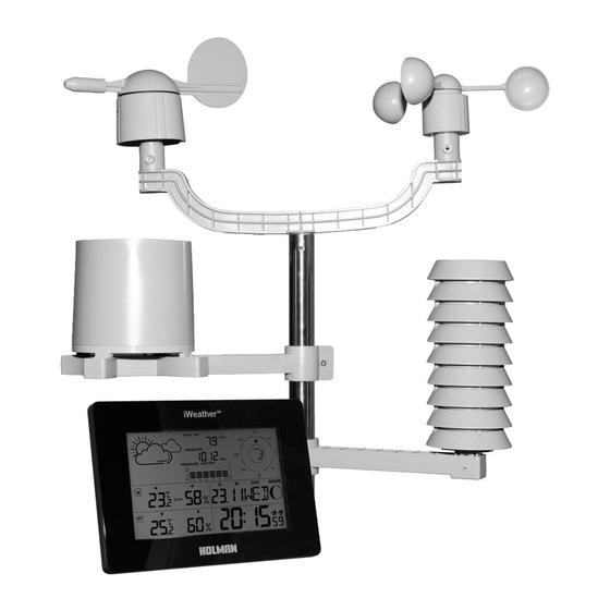
Table of Contents General Information Package Contents Technical Details Outdoor Sensor Glossary Assembling the Sensor Unit 1) Fit Wind Speed Sensor 2) Fit the Wind Direction Sensor 3) Mounting the Rain Gauge 4) Mounting the Plastic Brackets 5) Mounting the Thermo Hygro Sensor 6) Connecting the sensors to the Thermo Hygro Sensor 7) Adding the Housing to the Thermo Hygro Sensor Installing the Batteries... -
Page 3: General Information
General Information Thank you for purchasing the HOLMAN Aspect Wireless Data Centre WS5029 - Weather Station, Please read the operating instructions carefully to familiarise yourself with the features and modes of operation before using the instrument. NOTE: Always remember to use high quality batteries & change them at least once per year. -
Page 4: Glossary
Glossary 1. Weather Forecast 8. Date 15. RCC symbol (not applicable in 21. Outdoor temperature Australia) 2. Living space humidity 9. Wind speed 22. Outdoor temperature alert 16. Summer time (not applicable 3. Indoor humidity trend 10. Month 23. RF symbol in Australia) 11. -
Page 5: Assembling The Sensor Unit
Assembling The Sensor Unit Assembly of the Weather Station parts may take a little time. The following procedure is recommended for assembling and installing the sensor unit. Please refer to below diagram through the duration of the assembly steps. WIND DIRECTION SENSOR WIND SPEED SENSOR HOUSE THERMO... -
Page 6: Fit The Wind Direction Sensor
Assembling The Sensor Unit 2) Fit the Wind Direction Sensor (F) to the other end of the ‘U Shaped’ plastic bracket (A) and connect the cable (J) from the Wind Speed Sensor (E) Insert the cable from the Wind Speed Sensor (E) into the socket in the base of the Wind Direction Sensor (F). -
Page 7: Mounting The Thermo Hygro Sensor
Assembling The Sensor Unit 5) Mount the Thermo Hygro Sensor (H) to the plastic bracket (C) 6) Connect the Wind Direction Sensor (F) and Rain Gauge (G) into the Thermo Hygro Sensor (H) Connect the remaining cable (K) from the Wind Direction Sensor (F) into the socket labelled “WIND”... -
Page 8: Installing The Batteries
Powering Up the Weather Station Note: It is very important that this process is done correctly. The internal and external units must connect through the wireless communication system and the initial power up routine allows this to happen. It is very important both units have the batteries installed within 3 minutes of each other. You can complete the assembly of the outside sensor unit before the batteries are installed or you can install the batteries before you assemble the sensor unit. -
Page 9: Checking Wireless Connection
Checking Wireless Connection Checking the Wireless Connection is Achieved & Maintained hygrometer module and the internal receiver. Make sure the low battery indicator on the internal receiver does not show the batteries are low. Low batteries can cause the wireless connection to fail. - Page 10 Checking Wireless Connection 4) Before installing the outside unit, test that the wireless connection is made. i) Hold the “ALARM” button on the internal unit for 3 seconds. approximately 3 minutes (See Picture 3). iii) the batteries into the external thermometer / hygrometer unit is transmitting.
-
Page 11: Barometer Information
Checking Wireless Connection 5) Once the units are communicating then install the outside unit. When placing both the inside and outside units remember they are subject to interference. Try to:- i) Install both units as close as possible to each other. iii) possible. -
Page 12: Installation Of The Weather Vane
Once the outdoor sensor is assembled and the wireless connection is working you need to install the sensor in a suitable location. Hints for Installation unimpeded. 2) A good place is on a sewer vent pipe that goes above the roof line of the house or shed. stainless steel pole in place, ensuring the sensors are located above the vent pipe. -
Page 13: Programming The Internal Main Unit
Programming the Internal Main Unit 1) Introduction Once the sensor unit is installed it is important to set the main internal receiver unit. There is a lot of information shown on this display unit and most of the measurements can be displayed in more than one measurement standard. -
Page 14: Initial Adjustments
Programming the Internal Main Unit 3) Initial Adjustments the height above or below sea level. “ ” or “ ” buttons. This adjustment is necessary to ensure the barometric pressure reading is accurate. This is because the barometric pressure decreases with altitude. Once adjusted push the Snooze/Light (f) button. -
Page 15: Setting The Time, Date And All Other Modal Conditions
Programming the Internal Main Unit Setting the Time, Date, ºC or ºF, Pressure in hPa or inhg & Rainfall in mm or in more than 20 seconds without adjusting a setting the unit will automatically default out of the programming cycle. If this happens you must start again. To start hold the ‘MODE’... -
Page 16: Daily Alarm Set-Up
Programming the Internal Main Unit Hint: pressed for 20 seconds. 5) Daily alarm set-up ‘MODE’ to switch from the time display to A1 display. ‘MODE’ “ ” or “ ” to select the hour then press ‘MODE “ ” or “ ”... -
Page 17: Max. / Min., Indoor / Outdoor, Temp & Humidity
Programming the Internal Main Unit 12/24 hours mode please follow the manual set-up to select 8) Max./ Min. for the indoor/outdoor temperature and humidity “ ” to display the indoor/outdoor max./min. temperature and humidity, hold “ ” for more than 3 seconds to delete the max./min. readings. Temperature alert set-up “ALERT”... -
Page 18: Weather Forecast
Programming the Internal Main Unit 9) Weather forecasts These are determined from the barometric pressure readings. Sometimes they may vary from the actual weather. There are 5 weather forecasts each of which are depicted in picture form. It can take a few days for the forecaster to accurately predict the future weather. This is because the forecaster is based on the changes in barometric pressure. -
Page 19: Moon Phase Display
Programming the Internal Main Unit Illumination “SNOOZE/LIGHT” button to activate the screen backlight for 8 seconds. 12) Moon phase display The weather station uses saved data to show the moon phase A: Full moon B: Decreasing 3/4 C: Last half D: Decreasing 1/4 E: New moon F: Increasing 1/4... - Page 20 We recommend registering your new product on our website. This will ensure we have a copy of your purchase and activate an extended warranty. Keep up to date to with relevant product information and special offers available through our newsletter. www.holmanindustries.com.au/product-registration/ Thanks again for choosing Holman...
Need help?
Do you have a question about the Aspect WS5029 and is the answer not in the manual?
Questions and answers