
Related Manuals for Holman iWeather WS5029


Summary of Contents for Holman iWeather WS5029
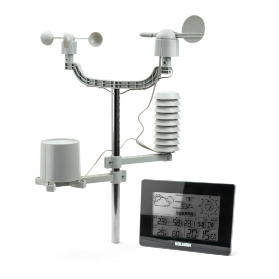
- Page 1 Professional Weather Station with Wireless Weather Wane For more information regarding this product and to watch the video of how it works please scan the QR code with your mobile device Instruction Manual Product Code: WS5029...
-
Page 2: Table Of Contents
Table of Contents General Information Package Contents Technical Details Outdoor Sensor Glossary Assembling the Sensor Unit 1) Fit Wind Speed Sensor 2) Fit the Wind Direction Sensor 3) Mounting the Rain Gauge 4) Mounting the Plastic Brackets 5) Mounting the Thermo Hygro Sensor Installing the Batteries 1) Internal Main Display Unit 2) External Sensor Unit... -
Page 3: General Information
General Information Thank you for purchasing the HOLMAN iWeather WS5029 - Weather Station, Please read the operating instructions carefully to familarize yourself with the features and modes of operation before using the instrument. NOTE: Always remember to use high quality batteries & change them at least once per year. -
Page 4: Glossary
Glossary 1. Weather Forecast 8. Date 15. RCC symbol (not applicable in 21. Outdoor temperature Australia) 2. Living space humidity 9. Wind speed 22. Outdoor temperature alert 16. Summer time (not applicable 3. Indoor humidity trend 10. Month 23. RF symbol in Australia) 4. -
Page 5: Assembling The Sensor Unit
Assembling The Sensor Unit Assembly of the Weather Station parts may take a little time. The following procedure is recommended for assembling and installing the sensor unit. 1) Fit the Wind Speed Sensor to the ‘U Shaped’ plastic bracket (labelled ‘1’ in illustration on page 4) Insert the “Wind Buckets”... -
Page 6: Mounting The Rain Gauge
Assembling The Sensor Unit The following diagram shows how the parts go together. WIND SPEED WIND DIRECTION RAIN GAUGE THERMO HYGRO SENSOR 3) Mount the Rain Gauge on the bracket with 4 screws holes (labelled ‘2’ in illustration above) Place the ‘bucket’ into the bracket & fix the 4 bolts &... -
Page 7: Mounting The Plastic Brackets
Assembling The Sensor Unit 4) Mount the plastic brackets onto the stainless steel mast (Please refer to illustration opposite) Starting at the top, insert the ‘U Shaped’ plastic bracket (labelled 1) into the top of the stainless steel pole & fix with a bolt & nut. Slide plastic bracket (labelled 2) with the Rain gauge onto the pole from the bottom and secure with a bolt and nut. -
Page 8: Installing The Batteries
Powering Up the Weather Station Note: It is very important that this process is done correctly. The internal and external units must connect through the wireless communication system and the initial power up routine allows this to happen. It is very important both units have the batteries installed within 3 minutes of each other. You can complete the assembly of the outside sensor unit before the batteries are installed or you can install the batteries before you assemble the sensor unit. -
Page 9: Checking Wireless Connection
Checking Wireless Connection Checking the Wireless Connection is Achieved & Maintained 1) It is very important to install new high quality batteries in both the outside thermometer / hygrometer module and the internal receiver. Make sure the low battery indicator on the internal receiver does not show the batteries are low. - Page 10 Checking Wireless Connection 4) Before installing the outside unit, test that the wireless connection is made. i) Hold the “ALARM” button on the internal unit for 3 seconds. ii) The RF Symbol will flash on the LCD for approximately 3 minutes (See Picture 3). iii) While this is flashing insert (within 3 minutes) the batteries into the external thermomter / hygrometer (shown in picture 1).
-
Page 11: Barometer Information
Checking Wireless Connection 5) Once the units are communicating then install the outside unit. When placing both the inside and outside units remember they are subject to interference. Try to:- i) Install both units as close as possible to each other. ii) Try and avoid outside interference by not placing them near computers, T.V.’s or T.V. -
Page 12: Installation Of The Weather Vane
Installation of the Weather Vane Once the outoor sensor is assembled and the wireless connection is working you need to install the sensor in a suitable location. Hints for Installation 1) The sensor needs to be installed in ‘Free Air’ where the wind is flowing freely and rainfall is unimpeeded. -
Page 13: Programming The Internal Main Unit
Programming the Internal Main Unit 1) Introduction Once the sensor unit is installed it is important to set the main internal receiver unit. There is a lot of information shown on this display unit and most of the measurements can be displayed in more than one measurement standard. -
Page 14: Initial Adjustments
Programming the Internal Main Unit 3) Initial Adjustments When you first instal the batteries the first adjustment you can make is the “altitude setting”. You will note that the pressure will display a flashing number. This reading is in metres and refers to the height above or below sea level. -
Page 15: Setting The Time, Date And All Other Modal Conditions
Programming the Internal Main Unit Setting the Time, Date, ºC or ºF, Pressure in hPa or inhg & Rainfall in mm or in To make these adjustments you must work through all the settings in sequence. If you stop for more than 20 seconds without adjusting a setting the unit will automatically default out of the programming cycle. -
Page 16: Daily Alarm Set-Up
Programming the Internal Main Unit Hint: • The clock automatically changes from set-up mode to time display mode if no keys are pressed for 20 seconds. 5) Daily alarm set-up Press ‘MODE’ to switch from the time display to A1 display. •... -
Page 17: Max. / Min., Indoor / Outdoor, Temp & Humidity
Programming the Internal Main Unit 12/24 hours mode • The time display can be in 12 (AM/PM) or 24 hours mode, please follow the manual set-up to select °C/°F temperature display • The temperature display can be in °C or °F, please follow the manual set-up to select. 8) Max./ Min. -
Page 18: Weather Forecast
Programming the Internal Main Unit 9) Weather forecasts These are determind from the barametric pressure readings. Sometimes they may vary from the actual weather. There are 5 weather forecasts each of which are depicted in picture form. It can take a few days for the forecaster to accurately predict the future weather. This is because the forecaster is based on the changes in barometric pressure. -
Page 19: Moon Phase Display
Programming the Internal Main Unit Illumination Press the “SNOOZE/LIGHT” button to activate the screen backlight for 8 seconds. • 12) Moon phase display The weather station uses saved data to show the moon phase A: New moon B: increasing crescent C: First half D: increasing 3/4 E: Full moon... -
Page 20: Warranty
Should you have any questions about this product or its operation please telephone our customer service help line on 1300 716 188. Holman offer a 1 year replacement warranty from the original date of purchase. To claim warranty the product must be returned with a copy of the original receipt.
Need help?
Do you have a question about the iWeather WS5029 and is the answer not in the manual?
Questions and answers