
Related Manuals for YOKOGAWA 701925 PBDH0500


Summary of Contents for YOKOGAWA 701925 PBDH0500
- Page 1 Userʼs Model 701925 Manual PBDH0500 Differential Probe IM 701925-01EN 1st Edition nbn Austria GmbH...
- Page 2 Product Registration Thank you for purchasing YOKOGAWA products. YOKOGAWA provides registered users with a variety of information and services. Please allow us to serve you best by completing the product registration form accessible from our website. https://tmi.yokogawa.com/ PIM 103-04E_A5...
-
Page 3: List Of Manuals
List of Manuals The following manuals are provided for the 701925, including this manual. Manual Title Manual No. Description Model 701925 IM 701925-01EN This manual. Explains PBDH0500 Differential Probe usage, specifications, User’s Manual and the handling precautions of the 701925. 701925 IM 701925-92Z1 Document for China PBDH0500 Differential Probe The “EN” and “Z1” in the manual numbers are the language codes. Contact information of YOKOGAWA offices worldwide is provided on the following sheet. Document No. Description PIM113-01Z2 Inquiry (List of worldwide contacts) 1st Edition: January 2021 (YMI) All Rights Reserved, Copyright © 2021 Yokogawa Test & Measurement Corporation IM 701925-01EN... - Page 4 • The contents of this manual are subject to change without prior notice as a result of continuing improvements to the instrument’s performance and functions. The figures given in this manual may differ from those that actually appear on your screen. • Every effort has been made in the preparation of this manual to ensure the accuracy of its contents. However, should you have any questions or find any errors, please contact your nearest YOKOGAWA dealer. • Copying or reproducing all or any part of the contents of this manual without the permission of YOKOGAWA is strictly prohibited. Trademarks • Adobe and Acrobat are either registered trademarks or trademarks of Adobe Systems incorporated.
-
Page 5: Checking The Package Contents
Checking the Package Contents The following accessories are included. If some of the contents are not correct or missing or if there is physical damage, contact the dealer that you purchased them from. • Probe unit: • Attachments: 1 set (see below) • Manuals: 1 set (see “List of Manuals,” provided earlier) • Carrying case: 1 Probe unit Manuals Attachments IM 701925-01EN... - Page 6 Checking the Package Contents No. Attachment Item Quantity 10-cm pair leads 5-cm pair leads Micro clip (red) Micro clip (black) Straight pin Angled pin Spring-type straight pin Spring-type angled pin Flanged pin 10 Contact, heat-shrink tube 10 each 11 Retaining cover 12 Ground extension lead 13 Marker tip* 8 colors x 1 each...
-
Page 7: Conventions Used In This Manual
Conventions Used in This Manual Improper handling or use can lead to injury to the user or damage to the instrument. This symbol appears on the instrument to indicate that the user must refer to the user’s manual for special instructions. The same symbol appears in the corresponding place in the user’s manual to identify those instructions. In the manual, the symbol is used in conjunction with the word “WARNING” or “CAUTION.” Calls attention to actions or conditions that could cause WARNING serious or fatal injury to the user, and precautions that can be taken to prevent such occurrences. Calls attention to actions or conditions that could cause CAUTION light injury to the user or damage to the instrument or user’s data, and precautions that can be taken to prevent such occurrences. Calls attention to information that is important for the Note proper operation of the instrument. French Une manipulation ou une utilisation incorrectes risquent de blesser l’utilisateur ou d’endommager l’instrument. Ce symbole apparaît sur l’instrument pour indiquer à l’utilisateur qu’il doit se reporter au manuel de l’utilisateur afin d’y lire les instructions spécifiques correspondantes. Ce même symbole apparaît à la section correspondante du manuel de l’utilisateur pour signaler lesdites instructions. Dans le manuel de l’utilisateur, ce symbole est accompagné des termes AVERTISSEMENT et ATTENTION. AVERTISSEMENT Attire l’attention sur des gestes ou des conditions susceptibles de provoquer des blessures graves (voire mortelles), et sur les précautions de sécurité pouvant prévenir de tels accidents. -
Page 8: Safety Precautions
Safety Precautions This product is designed to be used by a person with specialized knowledge. To use this product correctly and safely, make sure to observe the following safety precautions when handling the product. YOKOGAWA assumes no liability for the customer’s failure to comply with these safety precautions. This manual is part of the product and contains important information. Keep this manual in a safe place so that you can refer to it immediately when using the product until you dispose of the product. Also, before starting to use the probe, read the oscilloscope manual to thoroughly familiarize yourself with its specifications and handling. - Page 9 Do not operate with suspected failures Stop using the probe if you suspect that the probe is damaged. Consult your nearest YOKOGAWA dealer. Do not operate with a damaged signal cable If the signal cable is torn and the inner metal is exposed or if a color different from the outer sheath appears, stop using the cable.
- Page 10 Safety Precautions CAUTION Application and design of the product The product has not been designed or manufactured for applications in which high reliability is required over a long period of time. Protective structure The product is not dust or water resistant. Do not use it in areas with a lot of dust or near water. Usage and storage environment Avoid using or storing the product in an environment that does not meet the specifications, such as direct sunlight, high temperature and humidity, or condensation. Deformation or insulation...
- Page 11 Pour éviter les blessures et les risques d’incendie, n’utilisez pas la sonde dans une atmosphère de gaz ou des vapeurs inflammables ou explosifs. N’opérez pas en cas de défaillances suspectées Arrêtez d’utiliser la sonde si vous pensez qu’elle est endommagée. Consultez votre revendeur YOKOGAWA le plus proche. N’opérez pas avec le câble de signal endommagé Si le câble de signal est coupé et que le métal interne est exposé ou si une couleur différente de la gaine extérieure apparaît, arrêtez d’utiliser le câble. Ne démontez ou modifiez pas Ne démontez ou modifiez pas le produit. YOKOGAWA n’assume aucune responsabilité si vous démontez ou modifiez le produit. IM 701925-01EN...
- Page 12 Safety Precautions ATTENTION Application et conception du produit Le produit n’a pas été conçu ou fabriqué pour des applications dans lesquelles une fiabilité élevée est requise sur une longue période. Structure de protection Le produit n’est pas résistant à la poussière ou à l’eau. Ne l’utilisez pas dans des zones très poussiéreuses ou près de l’eau. Environnement d’utilisation et de stockage Évitez d’utiliser ou de stocker le produit dans un environnement qui ne répond pas aux spécifications, comme la lumière directe du soleil, les températures et l’humidité élevées ou la condensation.
-
Page 13: Regulations And Sales In Each Country Or Region
“Monitoring and control instruments” product. Do not dispose in domestic household waste. When disposing products in the EU, contact your local Yokogawa office in Europe. Authorized Representative in the EEA Yokogawa Europe B. V. is the authorized representative of Yokogawa Test & Measurement Corporation in the EEA for this product. To contact Yokogawa Europe B. V., see the separate list of worldwide contacts, PIM 113-01Z2. Disposal When disposing of this product, follow the laws and ordinances of your country or region. -
Page 14: Table Of Contents
Contents List of Manuals ..................i Checking the Package Contents ............iii Conventions Used in This Manual ............v Safety Precautions ................vi Regulations and Sales in Each Country or Region ......xi 1. Product Overview Overview of 701925 ................1 2. Configuration and Functions List of Standard Accessories ..............2 List of Optional Accessories (Sold Separately) ........2 Combinations of Accessories and Component Names ......3 Functions of Components ..............4 3. Operating Procedure Operating Precautions ................5 Preparation before Measurement ............7 Handling the Attachments .............. - Page 15 Contents Appendix 1. Frequency Characteristics Frequency Characteristics ............App-1 Appendix 2. Input Circuit and Accuracy Input Equivalent Circuit ..............App-4 Concept of DC Voltage Accuracy ..........App-4 xiii IM 701925-01EN...
-
Page 16: Product Overview
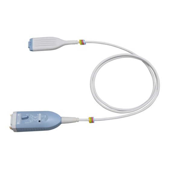
Overview of 701925 Model 701925 PBDH0500 Differential Probe is a differential input active probe with a wide bandwidth from DC to 500 MHz, used in combination with an oscilloscope that has a YOKOGAWA dedicated probe interface (hereinafter abbreviated as oscilloscope with probe interface).* The probe features excellent common mode rejection capability and allows direct observation of differential signals. Also, the probe is automatically... -
Page 17: Configuration And Functions
2. Configuration and Functions List of Standard Accessories The 701925 consists of the standard accessories listed below. The numbers correspond to the accessories shown on the next page. No. Standard Accessories Quantity 10-cm pair leads 5-cm pair leads Micro clip (red) Micro clip (black) Straight pin Angled pin Spring-type straight pin Spring-type angled pin Flanged pin 1, 2 10 Contact, heat-shrink tube 10 each 11 Retaining cover 12 Ground extension lead 13 Marker tip 8 colors x 1 each Connectable to a 0.64-mm square pin or a Φ0.65-mm pin. -
Page 18: Combinations Of Accessories And Component Names
2. Configuration and Functions Combinations of Accessories and Component Names Probe unit (length: 1.2 m) 13. Marker tip (8 colors x 1 each) Probe cable Probe head BNC output terminal To device under measurement Interface through various accessories spring pins Probe interface unit To oscilloscope with probe interface 12. -
Page 19: Functions Of Components
2. Configuration and Functions Functions of Components Probe head Various accessories are connected to the signal input terminals, and the probe head is connected to the device under measurement. Ground extension lead The ground lead is usually not used when measuring differential signals. Probe cable The probe cable connects the probe head and the probe interface unit. Marker tips All the 8-color tips are attached to the probe cable. The marker tips can be identified according to the channel display color of the connected oscilloscope. Cut and remove unnecessary color tips before use. Probe interface The probe interface unit is connected to an oscilloscope with probe interface. Output terminal The output terminal is a BNC connector. It is connected to an input terminal of the oscilloscope. Interface spring pins When the output terminal is connected, interface spring pins touch the pad on the oscilloscope interface board and the probe is automatically detected. The interface pins are also used to supply the probe’s power and a offset voltage. Latch release lever When disconnecting the probe from the oscilloscope, use the latch release lever to unlock the probe output terminal connected to the oscilloscope input terminal. The lock can be released while pushing the lever to the UNLOCK side. -
Page 20: Operating Procedure Operating Precautions
3. Operating Procedure Operating Precautions WARNING • Use this probe only with YOKOGAWA’s oscilloscopes with probe interface. Even with YOKOGAWA’s oscilloscopes, this probe can be used only when specified as a connectable accessory. Also, use this probe only with standard or optional accessories sold separately. • Do not instantaneously or continuously apply a voltage exceeding the following maximum voltage values between the input and ground. Failure to follow this precaution may cause... - Page 21 • Utilisez la sonde uniquement avec les oscilloscopes de YOKOGAWA avec interface de sonde. Même avec les oscilloscopes de YOKOGAWA, la sonde ne peut être utilisée que si spécifiée comme accessoire connectable. Et utilisez la sonde uniquement avec des accessoires standard ou des accessoires en option vendus séparément.
-
Page 22: Preparation Before Measurement
3. Operating Procedure Preparation before Measurement Have the probe and an oscilloscope with probe interface ready. Insert the probe interface unit completely into the oscilloscope input, and confirm that the BNC connector and the interface spring pins are securely fastened. The latch click will be heard when the connectors lock into place. When the probe is connected to an oscilloscope with probe interface, the probe interface is automatically detected, and the probe’s attenuation ratio and the input coupling of the oscilloscope are set automatically Attach any of the provided attachments or self-made attachments to the signal input terminals of the probe head. - Page 23 3. Operating Procedure Pins The following four types of pins are available. They are suitable for measuring relatively high-frequency signals. Select the pin according to the position and the status of the device under measurement. • Straight pin • Angled pin • Spring-type straight pin • Spring-type angled pin Self-made extension lead An extension lead can be made with the self-made kit if a lead longer than the accessories is needed or When using a retaining cover to prevent the lead from coming out of the probe head. See “Creating an Extension Lead” for details. Note Because the probe input has high impedance, the inductance from the probe head to the device under measurement has a large effect on the measured results of high frequency signal components. When measuring signals with frequency components of 100 MHz or higher, it is recommended to use as short attachments as possible for both the positive and negative signal input terminals.
-
Page 24: Creating An Extension Lead
3. Operating Procedure Creating an Extension Lead Create an extension lead using the standard accessory kit. Device-under-Measurement End Pass a lead wire through a heat-shrink tube for a contact. The lead wire is not included. AWG 24 to 26 is recommended. The maximum diameter is 2.0 mm. Here, a damping resistor can be inserted between the lead wire and the contact as shown in the illustration below. Crimp or solder the core of the lead wire to the contact. A dedicated crimping tool is needed to crimp the lead wires. Cover the contact with the heat-shrink tube, and then apply heat with a drier to fix the tube in place. Lead wire (not included. AWG 24 to 26 recommended, maximum diameter 2.0 mm) Heat-shrink tube for a contact <When inserting a resistor>... - Page 25 3. Operating Procedure Probe Head End Pass the lead wire through the heat-shrink tube. The heat-shrink tube for the probe-head end is not included. It must be obtained separately Solder the core wire of the lead wire to the flanged pin Cover the flanged pin with a heat-shrink tube, and then apply heat with a drier to fix the tube in place. Flanged pin Lead wire Heat-shrink tube (not included) Core wire 4.0 mm (soldering Solder not allowed) φ2.0 mm or less Cover with a heat-shrink tube Note • If solder gets into the soldering-not-allowed part (4 mm from the tip of the flanged pin), the probe may be damaged. Also, do not cover the part with the heat-shrink tube.
- Page 26 3. Operating Procedure Flange Align the + and − markings on the retaining cover to those on the probe head, and attach the retaining cover to the probe head. Check that the retaining cover’s left and right latches are securely locked. Removing the Retaining Cover While pinching the retaining cover at the top and bottom, remove the cover from the probe head Note • The retaining cover can only be used with a flanged pin that is included in the package • The probe’s ground terminal cannot be used if you are using the retaining cover...
-
Page 27: Using The Ground Extension Lead
3. Operating Procedure Using the Ground Extension Lead CAUTION Connect the ground extension lead only to the common ground. If measuring a floating circuit, do not use the ground terminal. Doing so may damage the measuring system or the device under measurement. French ATTENTION Connectez le câble d'extension de terre uniquement à la terre commune. N'utilisez pas la borne de terre si vous mesurez un circuit flottant. Cela pourrait endommager le système de mesure ou l'appareil sous mesure. -
Page 28: Example Of Connecting The Attachments
3. Operating Procedure Example of Connecting the Attachments Using 10-cm Pair Leads with Micro Clips Using 5-cm Pair Leads Using Pins (Straight, Angled, Spring-type Straight or Angled) IM 701925-01EN... -
Page 29: Warm-Up And Offset Voltage Adjustment
3. Operating Procedure Warm-up and Offset Voltage Adjustment Warm-up Immediately after connecting the probe, the heat emitted by the probe itself causes the offset voltage to drift. After turning on the power, warm up the probe for at least 30 minutes to stabilize it. Offset Voltage Adjustment CAUTION Do not apply excessive force to the offset voltage adjustment screw. Doing so may damage the internal variable resistor. -
Page 30: Product Specifications Electrical Specifications
4. Product Specifications Electrical Specifications The electrical specifications are those after 30 minutes of warm-up in the standard operating environment. Item Specifications Frequency band DC to 500 MHz (–3 dB) Attenuation ratio 50:1 DC voltage accuracy ±2 % of differential input voltage (at 50 Ω load) Input capacitance 1.1 pF (relative to ground, typical) Input resistance 1 MΩ ±3 % (relative to ground) Output impedance 50 Ω (typical) Maximum differential input voltage ±25 V (DC + ACpeak) 5, 6 Maximum operating input voltage ±35 V (DC + ACpeak) Maximum non-destructive input ±100 V (instantaneous) voltage Residual noise 300 μVrms (at probe output, typical) Residual offset voltage ±10 mV (at probe output, after ADJUST) Common mode rejection ratio –35 dB (DC to 1 MHz) (CMRR) –30 dB (1 MHz to 10 MHz) –26 dB (10 MHz to 100 MHz) –20 dB (100 MHz to 300 MHz) 1 See the table of General Specifications, provided later, for the standard... -
Page 31: Input Voltage Derating By Frequency
4. Product Specifications Input Voltage Derating by Frequency WARNING As the frequency of the input signal increases, the maximum input voltage of the probe decreases. French AVERTISSEMENT Lorsque la fréquence du signal d'entrée augmente, la tension d'entrée maximale de la sonde diminue. Input voltage derating by frequency 1000 Frequency [MHz] IM 701925-01EN... -
Page 32: Input Voltage Range
4. Product Specifications Input Voltage Range Vin- Negative signal input terminal Use the probe within this range. –35V Vin+ Positive signal input terminal –35V IM 701925-01EN... -
Page 33: General Specifications
4. Product Specifications General Specifications Item Specifications Probe length Approx. 1.2 m Weight Approx. 90 g Standard power supply voltage* ±5 V ±5 % Power consumption 120 mA (at ±5 V) Connector type Standard operating Temperature 23 °C ±5 °C environment Humidity 55 % ±10 % RH (no condensation) Operating environment Temperature 5 °C to 40 °C Humidity 20 % to 80 % RH (no condensation) Altitude 2000 m or less Storage environment Temperature –20 °C to +60 °C Humidity 20 % to 80 % RH (no condensation) Altitude 3000 m or less Warm-up time 30 minutes or more Calibration period 1 year recommended * Supplied through the interface pins from the oscilloscope with probe interface. - Page 34 Appendix 1. Frequency Characteristics Frequency Characteristics The probe’s frequency characteristics vary depending on the attachment that is used and how the lead wires are connected. The measured frequency characteristics when using typical attachments are shown below. The frequency characteristics when using pair leads and pair leads with micro clips have been measured with two lead wires running in parallel. Using Straight Pins Straight pins 1000 10000...
- Page 35 Appendix 1. Frequency Characteristics Using 5-cm Pair Leads 5-cm pair leads 1000 10000 Frequency [MHz] Using 5-cm Pair Leads with Micro-Clips 5-cm pair leads with micro-clips 1000 10000 Frequency [MHz] App-2 IM 701925-01EN...
- Page 36 Appendix 1. Frequency Characteristics Using 10-cm Pair Leads 10-cm pair leads 1000 10000 Frequency [Hz] Using 10-cm Pair Leads with Micro-Clips 10-cm pair leads with micro-clips 1000 10000 Frequency [MHz] App-3 IM 701925-01EN...
- Page 37 Appendix 2. Input Circuit and Accuracy Input Equivalent Circuit Positive signal input terminal Approx. 1.1 pF 1 MΩ Approx. 1.1 pF 1 MΩ Negative signal (–) input terminal Concept of DC Voltage Accuracy Input voltage Maximum operating input voltage Tolerance Positive input Vin+ Differential voltage tolerance:...
- Page 38 Aufgrund laufender Weiterentwicklungen sind Änderungen der Spezifikationen vorbehalten. Alle Angaben vorbehaltlich Satz- und Druckfehler. nbn Austria GmbH Riesstraße 146, 8010 Graz Tel. +43 316 40 28 05 | Fax +43 316 40 25 06 | nbn @ nbn. at | www. nbn. at...
Need help?
Do you have a question about the 701925 PBDH0500 and is the answer not in the manual?
Questions and answers