Table of Contents
Advertisement
Quick Links
Advertisement
Table of Contents

Related Manuals for YOKOGAWA PX8000


Summary of Contents for YOKOGAWA PX8000
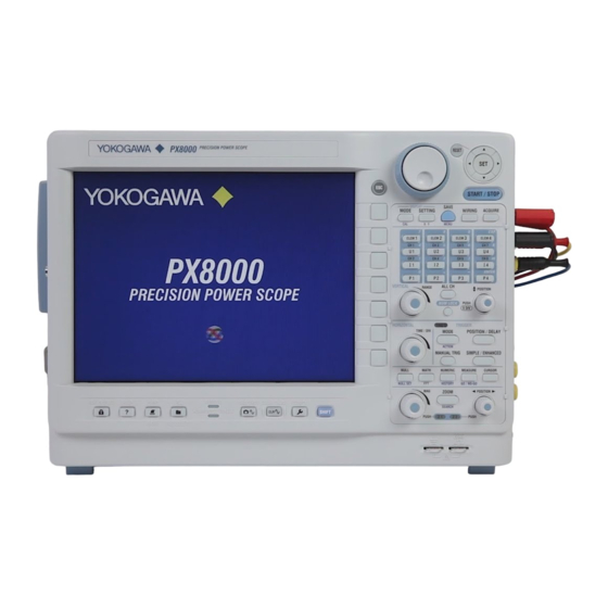
- Page 1 PX8000 Precision Power Scope IM PX8000-02EN 6th Edition...
- Page 2 Thank you for purchasing the PX8000 Precision Power Scope (hereafter referred to as the PX8000). This User’s Manual explains how to use the PX8000. To ensure correct use, please read this manual thoroughly before beginning operation. Keep this manual in a safe place for quick reference in the event a question arises. The following manuals, including this one, are provided as manuals for the PX8000.
- Page 3 Revisions • January 2014 1st Edition • January 2014 2nd Edition • August 2014 3rd Edition • December 2015 4th Edition • June 2017 5th Edition • October 2017 6th Edition IM PX8000-02EN...
-
Page 4: Conventions Used In This Manual
Note Calls attention to information that is important for the proper operation of the instrument. Unit Denotes 1000. Example: 100 kHz (frequency) Denotes 1024. Example: 720 KB (file size) IM PX8000-02EN... -
Page 5: Key And Jog Shuttle Operations
Press SHIFT. The SHIFT key illuminates to indicate that the keys are shifted. Now you can select the setup menus written in purple below the keys. Press the key that you want to display the setup menu of. IM PX8000-02EN... - Page 6 If you press RESET when you are using the jog shuttle to set a value or select an item, the setting is reset to its default value (depending on the operating state of the PX8000, the setting may not be reset).
- Page 7 To exit from the list, press ESC. Press SET to select the item that you want to set. How to Clear Setup Dialog Boxes Press ESC to clear the setup dialog box from the screen. IM PX8000-02EN...
-
Page 8: Entering Values And Strings
After you enter the value, press ENTER to confirm it. Use the keypad to enter the value. Note Some items that you can set using the jog shuttle are reset to their default values when you press the RESET key. IM PX8000-02EN... - Page 9 MS-DOS limitations: AUX, CON, PRN, NUL, CLOCK, COM1 to COM9, and LPT1 to LPT9 For details on file name limitations, see the Features Guide, IM PX8000-01EN. • When a character string is confirmed, it is stored in a list of previously entered strings. Up to 50 character strings are stored.
-
Page 10: Table Of Contents
Triggering on a Pulse Width Trigger (Enhanced) ............3-15 3.14 Triggering on a Wave Window Trigger (Enhanced) ............3-17 Manual trigger 3.15 Triggering the PX8000 Manually (Manual Trigger) ............3-18 Chapter 4 Waveform Acquisition Setting Conditions for Waveform Acquisition ..............4-1 Starting and Stopping Waveform Acquisition ..............4-3... - Page 11 Chapter 15 Waveform Computation 15.1 Performing Addition, Subtraction, Multiplication, and Division ........15-1 15.2 Performing Binary Conversion ..................15-2 15.3 Shifting the Phase ......................15-3 15.4 Displaying the Power Spectrum ..................15-4 15.5 Performing User-Defined Computations ................ 15-5 IM PX8000-02EN...
- Page 12 Connecting the PX8000 to a Network ................23-1 23.2 Configuring TCP/IP Settings ................... 23-3 23.3 Accessing the PX8000 from a PC (FTP Server) ............23-4 23.4 Connecting to a Network Drive ..................23-5 23.5 Using SNTP to Set the Date and Time ................23-6 Chapter 24 Other Operations 24.1...
- Page 13 Contents Chapter 25 Messages and Self-Test 25.1 Messages and Corrective Actions .................. 25-1 25.2 Carrying Out Self-Tests (Selftest) ................... 25-8 25.3 Viewing System Information (Overview)................25-11 Index IM PX8000-02EN...
-
Page 14: Chapter 1 Fundamental Measurement Conditions
• You cannot set the wiring units for larger element numbers before the wiring units for smaller element numbers. IM PX8000-02EN... - Page 15 • Set the correction value for voltage signals. • Set the correction value for current signals. • Set the correction value for external current sensor signals. To set or execute on all channels, set or execute the items in the All row. IM PX8000-02EN...
-
Page 16: Configuring Power Measurement Element Settings
ON, the CT ratio will end up being multiplied on top of the result. To avoid the influence of the CT ratio, set the CT ratio to 1.0000. IM PX8000-02EN... -
Page 17: Setting The Motor Mode
When motor mode is on Set Motor Mode to OFF. Set Motor Mode to ON. Set the function name. Set the scaling. Set the unit. Set the synchronization source Set the synchronization source (U1-U4, I1-I4, External, None). (U1-U4, I1-I4, External, None). IM PX8000-02EN... -
Page 18: Chapter 2 Vertical And Horizontal Control
The U key whose display setting is ON illuminates. If the U key is not illuminated, you can press it to turn on the waveform display and the key. If the U key is illuminated, you can press it to turn off the waveform display and the key. IM PX8000-02EN... - Page 19 Changing the measurement range of one element will change that of the other element to the same value.* * If independent element configuration (see section 1.1) to ON, you need to set the measurement range for each element. IM PX8000-02EN...
- Page 20 Using the Upper/Lower soft key and the jog shuttle, set the voltage at the top edge of the waveform screen (upper limit) and the voltage at the bottom edge of the screen (lower limit) to set the waveform vertical position. Set the upper and lower limits of the display range. IM PX8000-02EN...
-
Page 21: Configuring Current Measurements
The I key whose display setting is ON illuminates. If the I key is not illuminated, you can press it to turn on the waveform display and the key. If the I key is illuminated, you can press it to turn off the waveform display and the key. IM PX8000-02EN... - Page 22 Changing the measurement range of one element will change that of the other element to the same value.* * If independent element configuration (see section 1.1) to ON, you need to set the measurement range for each element. IM PX8000-02EN...
- Page 23 • When the displayed waveform’s measurement range and the measurement range that you have set are the same, only the bottom row is displayed. Use the RANGE knob to display the measurement range that is currently being set. Range status See page 2-5. IM PX8000-02EN...
- Page 24 Using the Upper/Lower soft key and the jog shuttle, set the current at the top edge of the waveform screen (upper limit) and the current at the bottom edge of the screen (lower limit) to set the waveform vertical position. Set the upper and lower limits of the display range. IM PX8000-02EN...
-
Page 25: Configuring Power Measurements
The P key whose display setting is ON illuminates. If the P key is not illuminated, you can press it to turn on the waveform display and the key. If the P key is illuminated, you can press it to turn off the waveform display and the key. IM PX8000-02EN... - Page 26 Using the Upper/Lower soft key and the jog shuttle, set the power at the top edge of the waveform screen (upper limit) and the power at the bottom edge of the screen (lower limit) to set the waveform vertical position. Set the upper and lower limits of the display range. IM PX8000-02EN...
-
Page 27: Configuring Sensor Input Voltage Measurements
Of the ELEM 2 to ELEM 4 keys, press the key corresponding to the slot in which the AUX module is installed. On the menu that appears, set Motor Mode to OFF. Set Motor Mode to OFF. Set the synchronization source. ► section 1.3 2-10 IM PX8000-02EN... - Page 28 Set the bandwidth limit (10kHz, 320kHz, 640kHz, 1.28MHz, 2MHz, 20kHz, 40kHz, 80kHz, 160kHz, Full). 320kHz, 640kHz, 1.28MHz, 2MHz, Full). Set the upper and lower pulse reference levels. Displays the first page Displays the first page of the menu of the menu 2-11 IM PX8000-02EN...
- Page 29 The frequency responses when the input coupling is set to AC and DC are shown below. Note that the PX8000 does not acquire low-frequency signals or signal components if the input coupling is set to AC as indicated in the figure below.
- Page 30 Set the input signal type to Pulse. Set the linear scaling mode P1-P2. Measured Measured values Retrieve the current values measured values Scale values Scale value Same feature as when linear scaling mode is set to AX+B 2-13 IM PX8000-02EN...
- Page 31 Upper unit value: 100, 200, 500, 1k, No display No display 2k, 5k, 10k, 20k, 50k, Lower value: Lower unit value: 100k, 200k, 500k, 1M Available option value of Unit specified on the AUX the RANGE knob setting screen 2-14 IM PX8000-02EN...
- Page 32 • You can set the vertical position to 0 div by pressing the knob. Vertical POSITION knob RANGE knob This indicates that you can press the vertical POSITION knob to set the vertical position to 0 div. 2-15 IM PX8000-02EN...
- Page 33 Using the Upper/Lower soft key and the jog shuttle, set the voltage at the top edge of the waveform screen (upper limit) and the voltage at the bottom edge of the screen (lower limit) to set the waveform vertical position. Set the upper and lower limits of the display range. 2-16 IM PX8000-02EN...
-
Page 34: Configuring Rotating Speed Measurements
Of the ELEM 2 to ELEM 4 keys, press the key corresponding to the slot in which the AUX module is installed. On the menu that appears, set Motor Mode to ON. Set Motor Mode to ON. Set the function name. Set the scaling coefficient. Set the unit. Set the synchronization source. ► section 1.3 2-17 IM PX8000-02EN... - Page 35 Set the bandwidth limit (10kHz, 320kHz, 640kHz, 1.28MHz, 2MHz, 20kHz, 40kHz, 80kHz, 160kHz, Full). 320kHz, 640kHz, 1.28MHz, 2MHz, Set the upper and lower pulse Full). reference levels. Displays the first page Displays the first page of the menu of the menu 2-18 IM PX8000-02EN...
- Page 36 When the input signal type is Pulse Set the input signal type to Pulse. Select the rotating speed unit (rps, rpm, rph). Set the number of pulses per rotation (1-9999). Same feature as when the input signal type is set to Analog 2-19 IM PX8000-02EN...
- Page 37 200, 500, 1k, 2k, 5k, No display No display 10k, 20k, 50k, 100k, Lower value: Lower unit value: 200k, 500k, 1M Available option value of Unit selected on the rotating the RANGE knob speed measurement setting screen 2-20 IM PX8000-02EN...
- Page 38 • You can set the vertical position to 0 div by pressing the knob. Vertical POSITION knob RANGE knob This indicates that you can press the vertical POSITION knob to set the vertical position to 0 div. 2-21 IM PX8000-02EN...
- Page 39 Using the Upper/Lower soft key and the jog shuttle, set the number of rotations at the top edge of the waveform screen (upper limit) and the number of rotations at the bottom edge of the screen (lower limit) to set the waveform vertical position. Set the upper and lower limits of the display range. 2-22 IM PX8000-02EN...
-
Page 40: Configuring Torque Measurements
Of the ELEM 2 to ELEM 4 keys, press the key corresponding to the slot in which the AUX module is installed. On the menu that appears, set Motor Mode to ON. Set Motor Mode to ON. Set the function name. Set the scaling coefficient. Set the unit. Set the synchronization source. ► section 1.3 2-23 IM PX8000-02EN... - Page 41 Set the bandwidth limit (10kHz, 320kHz, 640kHz, 1.28MHz, 2MHz, 20kHz, 40kHz, 80kHz, 160kHz, Full). 320kHz, 640kHz, 1.28MHz, 2MHz, Set the upper and lower pulse Full). reference levels. Displays the first page Displays the first page of the menu of the menu 2-24 IM PX8000-02EN...
- Page 42 Set the torque unit. Set the positive and negative rated torque signal values (-10000.0000 to 10000.0000). Set the positive and negative rated torque signals’ pulse signal values (1Hz-100000000Hz). Same feature as when the input signal type is set to Analog 2-25 IM PX8000-02EN...
- Page 43 100, 200, 500, 1k, No display No display 2k, 5k, 10k, 20k, Lower value: Lower unit value: 50k, 100k, 200k, Available option value of Unit selected on the torque speed 500k, 1M the RANGE knob measurement setting screen 2-26 IM PX8000-02EN...
- Page 44 • You can set the vertical position to 0 div by pressing the knob. Vertical POSITION knob RANGE knob This indicates that you can press the vertical POSITION knob to set the vertical position to 0 div. 2-27 IM PX8000-02EN...
- Page 45 Using the Upper/Lower soft key and the jog shuttle, set the torque at the top edge of the waveform screen (upper limit) and the torque at the bottom edge of the screen (lower limit) to set the waveform vertical position. Set the upper and lower limits of the display range. 2-28 IM PX8000-02EN...
-
Page 46: Displaying The Menu For Configuring All Channels
Use the jog shuttle to select the setting that you want to change, and then press SET to display the available options or an input box. To set all elements to the same setting at once, change the settings in the All column. Use the jog shuttle to select the item that you want to set. 2-29 IM PX8000-02EN... - Page 47 Press the Auxiliaries Copy to soft key to display the following screen. Set the copy source channel. Selects all channels except the copy source to be copy destinations Clears all channels from being copy destinations Select the channel check boxes separately to set the copy destination. Starts copying 2-30 IM PX8000-02EN...
-
Page 48: Configuring The Horizontal Axis (Time Axis)
Time scale for the displayed waveform Turn the TIME/DIV knob. Top row: Time scale for the displayed waveform Bottom row: Time scale that you have specified Use the TIME/DIV knob to display the time scale that is currently being set. 2-31 IM PX8000-02EN... -
Page 49: Chapter 3 Triggering
If the time axis is set to a value that would cause the display to switch to roll mode, the roll mode display will be enabled. When the PX8000 triggers, it begins recording data. When data has been acquired up to the amount specified by the set record length, the waveform display stops. -
Page 50: Setting The Trigger Position And Trigger Delay
“Trigger Delay (Delay)” POSITION/DELAY Menu Press POSITION/DELAY to display the following menu. Set the trigger position. Set the trigger position to 10%. Set the trigger position to 50%. Set the trigger position to 90%. Set the trigger delay. IM PX8000-02EN... -
Page 51: Setting The Trigger Hold Off
► Features Guide: “Trigger Hold Off (Hold Off)” SIMPLE/ENHANCED Menu Press SIMPLE/ENHANCED to display the following menu. Set the trigger hold off. Setting the Hold-off Time (Hold Off) The trigger hold-off feature temporarily stops the detection of the next trigger once a trigger has occurred. IM PX8000-02EN... -
Page 52: Triggering On An Edge Trigger (Simple)
Press SIMPLE/ENHANCED and then the Setting soft key to select Simple. The following menu appears. Set Setting to Simple. Set the trigger source (U1-U4, I1-I4, P1-P4, AUX3-AUX8). Set the trigger slope ( Set the trigger level. Set the trigger hysteresis ( Set the trigger hold off. ► section 3.3 IM PX8000-02EN... -
Page 53: Triggering On A Timer Trigger (Simple)
Set Source to Time. Set the date and time. Set the time interval. Setting the Date and Time (Date/Time Setup) Press the Date/Time Setup soft key to display the following screen. Set the date and time. Confirms the date and time IM PX8000-02EN... -
Page 54: Triggering On An External Trigger (Simple)
SIMPLE External Menu Press SIMPLE/ENHANCED and then the Setting soft key to select Simple. The following menu appears. Set Setting to Simple. Set Source to External. Set the trigger slope ( Set the trigger hold off. ► section 3.3 IM PX8000-02EN... -
Page 55: Triggering On A Power Line Signal (Simple)
► Features Guide: “Power Line Signal (Line)” SIMPLE Line Menu Press SIMPLE/ENHANCED and then the Setting soft key to select Simple. The following menu appears. Set Setting to Simple. Set Source to Line. Set the trigger hold off. ► section 3.3 IM PX8000-02EN... -
Page 56: Enhanced Trigger
Set the state condition (H, L, or X (do not use as a trigger source)). Set the trigger level. Set the hysteresis ( Set the state condition achievement conditions (Enter, Exit). Set the number of times state condition B must be met. IM PX8000-02EN... -
Page 57: Triggering On An A Delay B Trigger (Enhanced)
Press the Set Pattern soft key to display the following menu. Set the state condition (H, L, or X (do not use as a trigger source)). Set the trigger level. Set the hysteresis ( Set the state condition achievement conditions (Enter, Exit). Set the delay time. IM PX8000-02EN... -
Page 58: Triggering On An Edge On A Trigger (Enhanced)
Set the state condition (H, L, or X (do not use as a trigger source)). Set the edge detection condition ( , —). Set the trigger level. Set the hysteresis ( Set the state condition achievement conditions (True, False). 3-10 IM PX8000-02EN... -
Page 59: Triggering On An Or Or And Trigger (Enhanced)
Set the trigger level (set to the center value of the level width if the edge detection condition is set to IN or OUT). Set the level width (when the edge detection condition is set to IN or OUT). Set the hysteresis ( 3-11 IM PX8000-02EN... - Page 60 Set the trigger level (set to the center value of the level width if the achievement condition is set to IN or OUT). Set the level width (when the achievement condition is set to IN or OUT). Set the hysteresis ( 3-12 IM PX8000-02EN...
-
Page 61: Triggering On A Period Trigger (Enhanced)
Set the reference time.* * Set T1 and T2 when the determination mode is T1 < T < T2 or T <T1, T2 < T. Set Time when the determination mode is T < Time or T >Time. 3-13 IM PX8000-02EN... - Page 62 Setting the Reference Mode (Mode) Set what kind of relationship must be established between period T and the specified reference times (Time or T1 and T2) for the PX8000 to trigger. T < Time Period T must be shorter than the reference time (Time).
-
Page 63: Triggering On A Pulse Width Trigger (Enhanced)
Set the hysteresis ( Set the determination mode. Set the reference time.* * Set T1 and T2 when the determination mode is B Between. Set Time when the determination mode is B < Time, B >Time, or B TimeOut. 3-15 IM PX8000-02EN... - Page 64 Setting the Reference Mode (Mode) Set what kind of relationship must be established between the state condition B achievement time and the specified reference times (Time or T1 and T2) for the PX8000 to trigger. B < Time The PX8000 triggers when the achievement time is shorter than the reference time (Time), and the state condition changes from being met to not being met.
-
Page 65: Triggering On A Wave Window Trigger (Enhanced)
(Auto, U1-U4, I1-I4, P1-P4, AUX3-AUX8). Set the level for detecting the start and end points, and set the detection hysteresis.* * Set when the synchronization channel is U1 to U4, I1 to I4, P1 to P4, or AUX3 to AUX8. 3-17 IM PX8000-02EN... -
Page 66: Triggering The Px8000 Manually (Manual Trigger)
3.15 Triggering the PX8000 Manually (Manual Trigger) This section explains how to trigger the PX8000 manually. ► Features Guide: “Trigger Types (Type)” Press MANUAL TRIG. 3-18 IM PX8000-02EN... -
Page 67: Chapter 4 Waveform Acquisition
Set the trigger mode. ► section 3.1 Set the number of waveform acquisitions. When the time base is Ext Set the attenuation constant. Set the time base (Int, Ext). Set the pulse/rotation. Execute Logger Setup.* * A confirmation message will appear. IM PX8000-02EN... - Page 68 Envelope: Displays waveforms in envelope mode. You can set the number of waveforms to acquire with the jog shuttle. Average: Displays averaged waveforms. You can set the attenuation constant and the number of times to average with the jog shuttle. IM PX8000-02EN...
-
Page 69: Starting And Stopping Waveform Acquisition
Waveform Acquisition (START/STOP) Press START/STOP to start or stop waveform acquisition. When the START/STOP key is illuminated, the PX8000 is acquiring waveforms. Note If every numeric data (see chapter 6) is displayed as no data (−−−−−−−) even when you start waveform acquisition, check the following items. -
Page 70: Chapter 5 Display Mode
DISPLAY SETTING. For details on the different SETTING menus, see the following sections. NUMERIC SETTING menu ► section 6.1 WAVE SETTING menu ► section 8.1 BAR SETTING menu ► section 9.1 VECTOR SETTING menu ► section 10.1 IM PX8000-02EN... -
Page 71: Switching The Displayed Page
► section 7.1 • Is the trigger set properly? Trigger mode ► section 3.1 Trigger position and trigger delay ► section 3.2 Trigger hold off ► section 3.3 Trigger conditions according to trigger type ► sections 3.4 to 3.15 IM PX8000-02EN... - Page 72 Currently displayed page To the previous page To the previous page Up arrow key (▼) To the next page Down arrow key (▼) To the next page IM PX8000-02EN...
-
Page 73: Changing The Displayed Items On The 4-, 8-, And 16-Value Displays
* These settings are available on models with the harmonic measurement (/G5) option. Example of the 4 Items Display Note If every numeric data is displayed as no data (−−−−−−−), check the referenced sections under “Note” in section 6.1. IM PX8000-02EN... - Page 74 * The measurement functions displayed on the screen are cleared, and every numeric data is displayed as no data. Switching the Page To set items on pages that are not currently shown, switch to these pages. For details on how to switch pages, see section 6.1. IM PX8000-02EN...
-
Page 75: Changing The Displayed Items On The Matrix Display
Set the resetting of displayed items. * These settings are available on models with the harmonic measurement (/G5) option. Matrix Display Example Note If every numeric data is displayed as no data (−−−−−−−), check the referenced sections under “Note” in section 6.1. IM PX8000-02EN... - Page 76 * The measurement functions displayed on the screen are cleared, and every numeric data is displayed as no data. Switching the Page To set items on pages that are not currently shown, switch to these pages. For details on how to switch pages, see section 6.1. IM PX8000-02EN...
-
Page 77: Changing The All Items Display
If you switch to the Matrix display, you can change the measurement functions, elements, and wiring units using the displayed table (see section 6.3). • If every numeric data is displayed as no data (−−−−−−−), check the referenced sections under “Note” in section 6.1. IM PX8000-02EN... -
Page 78: Changing The Harmonics List Display (Option)
Set the element and wiring unit (Element 1-Element 4, ΣA, ΣB). Hrm Single List Display Example Measurement function side Harmonic order data side Note If every numeric data is displayed as no data (−−−−−−−), check the referenced sections under “Note” in section 6.1. IM PX8000-02EN... - Page 79 On the harmonics list displays, you can change the measurement function, element, and wiring unit for the selected list, but you cannot change these settings for each individual display item. Switching the Page You can switch the page to display other items. For details on how to switch pages, see section 6.1. IM PX8000-02EN...
-
Page 80: Setting The Custom Display
Set the number of items per page (1-192). • Any changes made to Total Items will change the Items Per Page setting, and vice-versa. • For details on how to switch pages, see section 6.1. Customize display items. Save the display configuration file. 6-10 IM PX8000-02EN... - Page 81 Set the save destination. ► section 22.3 Set the file name. ► section 22.3 Starts saving Note that if a file with the same name exists in the destination folder, it will be overwritten without warning. File names are not case-sensitive. 6-11 IM PX8000-02EN...
- Page 82 Example of Loading a File for the Custom Display Note After you properly load a display configuration file and a background file, if you restart the PX8000 and the same background file is not in the same location, the background will return to its default.
-
Page 83: Chapter 7 Numeric Computation
► section 4.2 • Is the trigger set properly? Trigger mode ► section 3.1 Trigger position and trigger delay ► section 3.2 Trigger hold off ► section 3.3 Trigger conditions according to trigger type ► sections 3.4 to 3.15 IM PX8000-02EN... -
Page 84: Setting The Calculation Period
Moves to the nearest zero-crossing Moves to the nearest zero-crossing position before the Start Position position after the Start Position while maintaining the cursor span Moves to the nearest zero-crossing position before the Start Position while maintaining the cursor span IM PX8000-02EN... -
Page 85: Setting Numeric Data Averaging
Press the Next 1/2 soft key to display the 2/2 menu. When averaging type is Exp Set the averaging type Set the attenuation constant (OFF, Exp, Lin). (2-64). When averaging type is Lin Set the averaging count (8-64). IM PX8000-02EN... -
Page 86: Setting User-Defined Functions
► Features Guide: “User-Defined Functions (User Defined Function)” NUMERIC Menu Press NUMERIC to display the following menu. Set Numeric Measure to ON. Displays the second page of the menu Press the Next 1/2 soft key to display the 2/2 menu. Set the user-defined function. IM PX8000-02EN... - Page 87 Displays the setup screen for user-defined functions F1 to F5 Displays the setup screen for user-defined functions F6 to F10 Displays the setup screen for user-defined functions F11 to F15 Displays the setup screen for user-defined functions F16 to F20 IM PX8000-02EN...
-
Page 88: Setting Apparent Power, Reactive Power, And Corrected Power Equations
Press NUMERIC to display the following menu. Set Numeric Measure to ON. Displays the second page of the menu Press the Next 1/2 soft key to display the 2/2 menu. Set the apparent power, reactive power, and corrected power equations. IM PX8000-02EN... - Page 89 (Type 1, Type 2, Type 3 Corrected power equation Set the applicable standard (IEC76-1(1976), IEC76-1(1993)). Set the coefficients (0.0001-9.9999). When Select standard is IEC76-1(1976), set coefficients P1 and P2. † These settings are available on models with the harmonic measurement (/G5) option. IM PX8000-02EN...
-
Page 90: Setting The Phase Difference Display Format
Press NUMERIC to display the following menu. Set Numeric Measure to ON. Displays the second page of the menu Press the Next 1/2 soft key to display the 2/2 menu. Set the phase difference display format (180 degrees, 360 degrees). IM PX8000-02EN... -
Page 91: Setting Harmonic Measurement Conditions
Set the distortion factor equation (1/Total, 1/Fundamental). Set the start point of harmonic measurement (−5.000div to 5.000div). Sets the start point (Start Position) of the numeric cursor computation range to the start point (Start Position) of harmonic measurement IM PX8000-02EN... -
Page 92: Chapter 8 Waveform Display
Set the interpolation method (OFF, Sine, Line, Pulse). Set the grid ( Turns the display of scale values on and off Turns the trace label display on and off Set the extra window (OFF, 1, 2, 3, 4, 5, 6, 7, 8, Auto). IM PX8000-02EN... - Page 93 When set to OFF: Blank If FFT1 is set to ON, FFT1 appears in the Math7 position. If FFT2 is set to ON, FFT2 appears in the Math8 position. Label: Blank Map: - Set the FFT waveform color. Disp: Blank IM PX8000-02EN...
-
Page 94: Using The Snapshot And Clear Trace Features
Snapshot waveforms remain on the screen until you execute a clear trace operation. Clear Trace (CLEAR TRACE) Press CLEAR TRACE to clear all the waveforms that are displayed on the screen. Note Click SHIFT+SNAPSHOT to clear only the snapshot waveforms. IM PX8000-02EN... -
Page 95: Chapter 9 Bar Graph Display (Option)
Set the harmonic order of the bar graph to measure with markers x and + (0-500). If you press this soft key and select both × Order and + Order, you can change both orders while maintaining the relationship between the two. IM PX8000-02EN... -
Page 96: Chapter 10 Vector Display (Option)
If you press this soft key to select both U Mag and I Mag, you can change both magnifications while maintaining the relationship between the two. Turns the numeric data display on and off 10-1 IM PX8000-02EN... -
Page 97: Chapter 11 X-Y Display
Turn the X-Y waveform on and off and set X-axis and Y-axis source waveforms. Set the start and end points (−5.00div to 5.00div). The end point must be greater than or equal to the start point. Turns the trace-clear-on-start on and off Displays the second page of the menu 11-1 IM PX8000-02EN... - Page 98 When X-Y Window 2 is selected, Set the X-Y waveforms of XY5 to XY8. Set the source waveform for the Y axis. Set the source waveform for the X axis. Turns the XY waveform display on and off 11-2 IM PX8000-02EN...
-
Page 99: Chapter 12 Zooming Waveforms
Zoom box 1 and zoom box 2 that are displayed in the Main window moves to the specified zoom positions. The waveforms in zoom box 1 are displayed in the Zoom 1 window; the waveforms in zoom box 2 are displayed in the Zoom 2 window. 12-1 IM PX8000-02EN... - Page 100 Zoom1 when the Zoom 1 window is on and the zoom range of Zoom2 when the Zoom 2 window is on. Displays the first page of the menu When both Zoom 1 and Zoom 2 window displays are on Select which zoom range: Zoom 1 or Zoom 2. 12-2 IM PX8000-02EN...
- Page 101 Moves to the left edge of the Main window Allocating Zoom Source Waveforms (Allocation) Press the Allocation soft key to display the following screen. Select the zoom source waveforms. The waveforms that can be selected are displayed. 12-3 IM PX8000-02EN...
- Page 102 • The zoom POSITION knob has a push switch. Push the knob to illuminate the Z1 indicator, Z2 indicator, or both indicators. When both the Z1 and Z2 indicators are illuminated, you can set both zoom windows to the same zoom position at the same time. 12-4 IM PX8000-02EN...
-
Page 103: Chapter 13 Cursor Measurement
The waveforms that you can select differ depending on the window that cursor measurements will be performed in. • T-Y: U1 to U4, I1 to I4, P1 to P4, AUX3 to AUX8, Math1 to Math8 • X-Y: XY1 to XY8 13-1 IM PX8000-02EN... -
Page 104: Measuring With Vertical Cursors
The waveforms that you can select differ depending on the window that cursor measurements will be performed in. • T-Y: All, U1 to U4, I1 to I4, P1 to P4, AUX3 to AUX8, Math1 to Math8 • X-Y: XY1 to XY8 13-2 IM PX8000-02EN... -
Page 105: Measuring With Marker Cursors (Marker)
(T-Y, X-Y, FFT).* Select the measurement items that you want to use. When the window is X-Y* * This is available when the X-Y window display or FFT window display is turned on. 13-3 IM PX8000-02EN... - Page 106 The waveforms that you can select differ depending on the window that cursor measurements will be performed in. • T-Y: OFF, U1 to U4, I1 to I4, P1 to P4, AUX3 to AUX8, Math1 to Math8 • X-Y: OFF, XY1 to XY8 • FFT: OFF, FFT1, FFT2 13-4 IM PX8000-02EN...
-
Page 107: Measuring With Angle Cursors (Degree)
(Cursor1 to Zoom1, Cursor1 to Zoom2, Cursor2 to Zoom1, Cursor2 to Zoom2) Set measurement items. Set the reference angle (1-720). Set the window in which cursor Select the measurement items that measurements will you want to use. be performed to T-Y. 13-5 IM PX8000-02EN... -
Page 108: Measuring With Horizontal And Vertical Cursors (H & V)
The waveforms that you can select differ depending on the window that cursor measurements will be performed in. • T-Y: U1 to U4, I1 to I4, P1 to P4, AUX3 to AUX8, Math1 to Math8 • X-Y: XY1 to XY8 13-6 IM PX8000-02EN... -
Page 109: Measuring With Peak Cursors (Peak)
Set the FFT2 measurement time period (−5div to 5div). The setting resolution varies depending on the number of FFT points. Set measurement items. Select the measurement items that Set Select Window you want to use. to FFT. 13-7 IM PX8000-02EN... -
Page 110: Chapter 14 Automated Measurement Of Waveform Parameters
The maximum number of data points that are measured is 100 Mpoint from Time Range 1. Turns cycle mode on and off If the measurement time period (the spacing between Time Range1 and Time Range2) is less than 1 cycle, the measured value will be “*****.” 14-1 IM PX8000-02EN... - Page 111 • When the Source Waveform Is U1 to U4, I1 to I4, P1 to P4, AUX3 to AUX8, Math1 to Math8 Select the measurement items that you want to use. • When the Source Waveform Is XY1 to XY8 Select the measurement items that you want to use. 14-2 IM PX8000-02EN...
- Page 112 Press the Copy to soft key to display the following screen. Copies the contents specified by measurement item (Item) to the selected waveforms (Trace) (U1-U4, I1-I4, P1-P4, AUX3-AUX8, Math1-Math8) Selects all waveforms Unselects all waveforms Starts copying 14-3 IM PX8000-02EN...
-
Page 113: Performing Normal Statistical Processing
Press MEASURE, the Mode soft key, and then the Statistics soft key to display the following menu. Set automated measurement to Statistics. Set the source waveform and configure the measurement items. ► section 14.1 Set the measurement time period. ► section 14.1 Turns cycle mode on and off ► section 14.1 14-4 IM PX8000-02EN... -
Page 114: Performing Cyclic Statistical Processing
U1 to U4, I1 to I4, P1 to P4, AUX3 to AUX8, Math1 to Math8: The PX8000 automatically measures the waveform parameters of all the source waveforms and performs statistical processing on the measured values once per cycle of the specified waveform. - Page 115 (Forward, Reverse) Displays the maximum value Displays the minimum value If scroll bars are displayed, you can press the arrow keys (▲, ▼, ◄, ►) to scroll the list. You can scroll vertically also using the jog shuttle. 14-6 IM PX8000-02EN...
-
Page 116: Chapter 15 Waveform Computation
Press a soft key from Math1 to Math8 to display the following screen. Select the operation (S1+S2, S1–S2, S1*S2, S1/S2). Select the computation source waveform (U1-U4, I1-I4, P1-P4, AUX3-AUX8, Math1-Math7). Set the unit. Set the label. Turns the waveform display on and off 15-1 IM PX8000-02EN... -
Page 117: Performing Binary Conversion
Select the computation source waveform (U1-U4, I1-I4, P1-P4, AUX3-AUX8, Math1-Math7). Set the upper and lower limits of the threshold. (Within ±5 div of the computation source waveform) Set the unit. Set the label. Turns the waveform display on and off 15-2 IM PX8000-02EN... -
Page 118: Shifting The Phase
Select function Shift(S1). Select the computation source waveform (U1-U4, I1-I4, P1-P4, AUX3-AUX8, Math1-Math7). Set the shift range (within ±(record length/2) of the computation source waveform). Set the unit. Set the label. Turns the waveform display on and off 15-3 IM PX8000-02EN... -
Page 119: Displaying The Power Spectrum
Select the computation source waveform (U1-U4, I1-I4, P1-P4, AUX3-AUX8, Math1-Math7). Set the unit. Set the label. Turns the waveform display on and off Configuring the FFT Set the number of FFT points and window function. ► section 15.5 15-4 IM PX8000-02EN... -
Page 120: Performing User-Defined Computations
Set the computation start and end points. ► sections 15.1 and 15.4 Displays the second page of the menu Press the Next 1/2 soft key to display the 2/2 menu. Set the FFT. Set the filters. Set the constant. Displays the first page of the menu 15-5 IM PX8000-02EN... - Page 121 Define an expression by combining computation source waveforms, operators, and functions. Enter a character string from the history. Character insertion position Deletes all characters Inserts a ) Move the character insertion position Deletes the previous character Confirms the expression you defined 15-6 IM PX8000-02EN...
- Page 122 Set this when the filter band is Band-Pass. Displays the cutoff frequency as a percentage of the sample rate in use. Defining Constants (Constant Setup) Press the Constant Setup soft key to display the following screen. Set the constant (−9.9999E+30-9.9999E+30). 15-7 IM PX8000-02EN...
-
Page 123: Displaying Fft Waveforms
Set the computation start point (−5div to -5div). The setting resolution varies depending on the display record length. Set the number of FFT points (1k, 2k, 5k, 10k, 20k, 50k, 100k). Displays the second page of the menu 16-1 IM PX8000-02EN... - Page 124 Set the calculation period (1%-100%). Set this when the window function is Exponential. * The available sub types vary depending on the spectrum type. Type Available Sub Types LS, CS, TF REAL, IMAG, MAG, LOGMAG, PHASE RS, PS, PSD MAG, LOGMAG 16-2 IM PX8000-02EN...
-
Page 125: Chapter 17 Go/No-Go Determination
Set the actions. Set the determination period (−5div to 5div). The setting resolution varies depending on the display record length. Time period 2 (Time Range2) must be greater than or equal to Time period 1 (Time Range1). 17-1 IM PX8000-02EN... - Page 126 Set the zone number (Zone1-Zone6). Set the determination logic (AND, OR). Set the action condition (Always, Fail, Success). Set the sequence (Single, Continue). Set the number of measurements (the number of waveform acquisitions) (Infinite, 1-65536). Turns external start on and off 17-2 IM PX8000-02EN...
- Page 127 Set the numeric data save destination. ► section 22.3 Set this when Save Numeric is selected for the action. Set the screen capture save destination. ► section 22.3 Set this when Save Image is selected for the action. 17-3 IM PX8000-02EN...
-
Page 128: Performing Go/No-Go Determination With Waveform Parameters
“Automated Measurement of Waveform Parameters” GO/NO-GO Menu Press SHIFT+MEASURE (GO/NO-GO) to display the following menu. Set the GO/NO-GO determination mode to Parameter. Set the judgment conditions. Set the actions. ► section 17.1 Set the determination period. ► section 17.1 17-4 IM PX8000-02EN... - Page 129 (Infinite, 1-65536). Turns external start on and off Setting Waveform Parameters (Item) You can use all automatically measured waveform parameters as judgment conditions. Up to 16 parameters set as judgment conditions can be determined simultaneously. ► section 14.1 17-5 IM PX8000-02EN...
-
Page 130: Setting Actions
Set the numeric data save destination. ► section 22.3 Set this when Save Numeric is selected for the action. Set the screen capture save destination. ► section 22.3 Set this when Save Image is selected for the action. 18-1 IM PX8000-02EN... - Page 131 When the specified number of measurement count (waveform acquisition count) is reached Measurement count (waveform acquisition count) ► section 4.1 or chapter 17 • When waveform acquisition is stopped with the START/STOP key When waveform acquisition is stopped with the START/STOP key, actions are executed once. 18-2 IM PX8000-02EN...
-
Page 132: Chapter 19 Searching Waveforms
Press the Setup soft key to display the following screen. Set the waveform to search (U1-U4, I1-I4, P1-P4, AUX3-AUX8). Set the reference level. Set the edge polarity ( Set the hysteresis ( Set the number of times to detect the conditions. 19-1 IM PX8000-02EN... - Page 133 Press the Execute soft key to execute the search. If the PX8000 finds points that match the search conditions (detected points), it shows detected point number numbers (0, 1, 2, etc.) from the left of the waveform display in the order that the points were detected.
-
Page 134: Searching For A Specific Time
Set the date and time (Year, Month, Day, Hour, Minute, Second, μSecond). Executing a Search (Execute) Press the Execute soft key to execute the search. The detected waveform appears in the zoom window with the specified time at the center. 19-3 IM PX8000-02EN... -
Page 135: Chapter 20 Displaying And Searching History Waveforms
To display all the history waveforms in acquisition memory again, turn the history waveform search feature off. • The averaging feature requires a certain amount of acquisition memory. If this is not available, you will not be able to display the Average Record. 20-1 IM PX8000-02EN... - Page 136 If many history waveforms are selected, it may take a long time to display all waveforms or average waveforms. If this happens, the icon appears at the top of the screen. To cancel the operation, set Display Mode to 1 Record. • History waveforms are cleared when you turn the power off. 20-2 IM PX8000-02EN...
-
Page 137: Searching History Waveforms
► Features Guide: “Search Condition Settings for Zone Searching (Search Setup)” “Search Condition Settings for Waveform Parameter Searching (Search Setup)” HISTORY Menu Press SHIFT+NUMERIC (HISTORY) to display the following menu. Set the search mode (OFF, Zone, Parameter). 20-3 IM PX8000-02EN... - Page 138 The maximum number of data points that are measured is 100 Mpoint from Time Range 1. Setting the Waveform to Search and the Parameter (Source) Press the Source soft key to display the following menu. Set the source waveform (U1-U4, I1-I4, P1-P4, AUX3-AUX8). Set the waveform parameter type. ► section 14.1 20-4 IM PX8000-02EN...
- Page 139 20.2 Searching History Waveforms Executing a Search (Execute Search) After setting the search conditions, press ESC to return to the HISTORY menu. Starts searching 20-5 IM PX8000-02EN...
-
Page 140: Chapter 21 Printing And Saving Screen Captures
This section explains how to load roll paper into the built-in printer (/B5 option). Printer Roll Paper Only use YOKOGAWA roll paper for the PX8000. When using the printer for the first time, use the roll paper supplied with the PX8000. When you need extra roll paper, please contact your nearest YOKOGAWA dealer. - Page 141 Print head Guide Close the printer cover and Align the ends of the roll paper with press LOCK at the center of the cover until you hear a click. the guides and set the roll in place. 21-2 IM PX8000-02EN...
-
Page 142: Printing On The Built-In Printer (Option)
21.2 Printing on the Built-in Printer (Option) This section explains the following settings for printing the image that is displayed on the PX8000 using the built-in printer (/B5 option). • Print destination • Comment ► Features Guide: “Printing from the Built-In Printer (BuiltIn; option)”... -
Page 143: Saving Screen Captures To Files
Displays the file list ► section 22.10 Set auto naming. ► section 22.3 Set the file name. ► section 22.3 Set a comment. ► section 22.3 Starting to Save Press PRINT to save the screen capture file to the specified folder. 21-4 IM PX8000-02EN... - Page 144 * This appears when the data format is set to PNG. When the data format is set to JPEG, the frame on/off setting appears. Starting to Save Press SAVE to save the screen capture file to the specified folder. 21-5 IM PX8000-02EN...
-
Page 145: Chapter 22 Saving And Loading Data
SD Memory Card CAUTION • Do not orient the SD memory card in the wrong direction, and force it into the PX8000. Doing so may damage the SD memory card and the PX8000. • Inserting and removing the SD memory card quickly (within the span of a second) may damage the PX8000. - Page 146 Insert the SD memory card into the slot. The front of the card should be facing you. The SD memory card slot is on the left side panel of the PX8000. If you are using an SD memory card that has a write-protection feature and you want to save data to or format the card, disable the write-protection feature before you insert the SD memory card into the PX8000.
- Page 147 You can connect/disconnect a USB cable at any time regardless of whether the PX8000 is on or off (hot-plugging is supported). Connect the type A connector of the USB cable to the PX8000, and connect the type B connector to the USB storage device. If you connect a USB storage device when the power switch is on, the device becomes available for use after the PX8000 identifies it.
-
Page 148: Formatting Storage Media
CAUTION • When you format a storage medium, all the data that is stored on the medium is deleted. • If a formatted storage medium cannot be detected by the PX8000, use the PX8000 to format the storage medium again. - Page 149 Storage Medium to Format (Media) SD memory card Upper USB: The USB storage device that is connected to the PX8000’s upper USB port (type A) for connecting peripheral devices. Lower USB: The USB storage device that is connected to the PX8000’s lower USB port (type A) for connecting peripheral devices.
-
Page 150: Saving Waveform Data
32-bit IEEE floating format. The extension is .FLD. You cannot load this type of data into the PX8000. If the file size would exceed 2 GB to create the file, it cannot be saved. 22-6... - Page 151 The extension is .WDF. This file is used to analyze waveforms using NI DIAdem. • You cannot load this type of data into the PX8000. • If the combination of the record length and the number of channels causes the file size to exceed 2 GB, the file cannot be created.
- Page 152 If there is a file with the same name in the save destination folder, you cannot save the data. Numbering: The PX8000 automatically adds a four-digit number between 0000 to 9999 after the common name specified using the File Name setting (up to four characters) when it saves files.
- Page 153 Math8 will not be saved. If you want to save Math1 to Math8, set History to One. Starting to Save (Execute Save) Press the Execute Save soft key to save the waveform data file to the specified folder. 22-9 IM PX8000-02EN...
- Page 154 If the number of files in the save destination folder exceeds 1000, a new folder is automatically created with the date and an incremented sequence number (000 to 999) as its name, and the data continues to be saved in the new folder. 22-10 IM PX8000-02EN...
-
Page 155: Saving Numeric Data
The save destination box appears at the bottom of the screen when the FILE Save menu is displayed. This box displays the file save destination, file name, and so on. Save destination Specified file name Auto naming type N indicating numeric data Extension 22-11 IM PX8000-02EN... - Page 156 Press the Execute Save soft key to save the numeric data file to the specified folder. SAVE Menu Press SHIFT+SAVE (MENU) to display the following menu. Set numeric data saving to ON. Set the save destination, file name, and data to save for numeric data. 22-12 IM PX8000-02EN...
- Page 157 Press SAVE to save the numeric data file to the specified folder. If Waveform Save or Image Save on the SAVE menu is set to ON, the waveform data or screen capture data will also be saved. 22-13 IM PX8000-02EN...
-
Page 158: Saving Setup Data
This box displays the file save destination, file name, and so on. Save destination Specified file name Auto naming type Extension Starting to Save (Execute Save) Press the Execute Save soft key to save the setup data file to the specified folder. 22-14 IM PX8000-02EN... -
Page 159: Saving Other Types Of Data
The save destination box appears at the bottom of the screen when the FILE Save menu is displayed. This box displays the file save destination, file name, and so on. Save destination Specified file name Auto naming type Extension 22-15 IM PX8000-02EN... - Page 160 • Setting the Color (Color) An screen capture is produced with a 65536-color palette. ON(Gray) An screen capture is produced with a 16-color grayscale palette. ON(Reverse) The screen background is not produced in color. A black-and-white screen capture is produced. 22-16 IM PX8000-02EN...
- Page 161 Sets whether to save the unit (ON, OFF). Sets whether to save time information (ON, OFF). Set the decimal point (Point, Comma). Set the save conditions for the results of automated measurement of waveform parameters. Starts saving 22-17 IM PX8000-02EN...
- Page 162 Set the decimal point (Point, Comma). Set the conditions for saving FFT analysis results. Starts saving Starting to Save (Execute Save) Press the Execute Save soft key to save the appropriate data file to the specified folder. 22-18 IM PX8000-02EN...
-
Page 163: Loading Waveform Data
If the current PX8000 module configuration is different from the modules configuration in the waveform data, you cannot load the waveform data. • Waveform data saved with a PX8000 model with large memory capacity cannot be loaded in to a model with small memory capacity. Clearing Loaded Waveforms Loaded waveforms are cleared in the following situations. -
Page 164: Loading Setup Data
Starting to Load (Execute Load) Press the Execute Load soft key to load the setup data file from the specified file. If the current PX8000 module configuration is different from the modules configuration in the setup data, you cannot load the setup data. -
Page 165: Loading Other Types Of Data
Starting to Load (Execute Load) Press the Execute Load soft key to load the snapshot waveform data file from the specified file. Clearing Loaded Waveforms Loaded waveforms are cleared when you press CLEAR TRACE or when you initialize the PX8000. 22-21 IM PX8000-02EN... -
Page 166: Performing File Operations
Create folders (directories). Use the arrow keys (▲▼) to move. Copy files and folders. Move files and folders. Operation menu File list Selects and unselects Use the arrow keys (◄►) to files and folders switch between the operation areas. 22-22 IM PX8000-02EN... -
Page 167: Display Format
Sort by date in ascending order. Sort by date in descending order. Display Format Select display format on the operation menu to display the following screens. Press SET to switch between display formats. List Display ( Display format Thumbnail Display ( 22-23 IM PX8000-02EN... - Page 168 USB-1: The second detected USB storage medium Network: Network Drive Note You can also change the storage medium by highlighting the storage medium (drive) you want to change to in the file list and pressing SET. 22-24 IM PX8000-02EN...
- Page 169 Use the keyboard to input the new file or folder name. Rename files and folders. File that you want to rename. Press ENTER on the keyboard or the Enter soft key to confirm the name you entered. 22-25 IM PX8000-02EN...
- Page 170 The procedure for selecting multiple files or folders at the same time to copy them is the same as the procedure for selecting multiple files or folders at the same time to delete them. For more details, see the note on page 22-25. • You can abort file copying. 22-26 IM PX8000-02EN...
- Page 171 The procedure for selecting multiple files or folders at the same time to move them is the same as the procedure for selecting multiple files or folders at the same time to delete them. For more details, see the note on page 22-25. 22-27 IM PX8000-02EN...
- Page 172 ALL RESET: Pressing this soft key clears all the selected files and folders. SET/RESET This soft key selects the file or folder in the file list that is highlighted or clears the selection. Selection marks (see page 22-22) are displayed to the left of the selected files. 22-28 IM PX8000-02EN...
-
Page 173: Chapter 23 Ethernet Communication
Ethernet Communication 23.1 Connecting the PX8000 to a Network This section explains how to connect the PX8000 to a network. Ethernet Interface Specifications There is a 1000BASE-T port located on the side panel of the PX8000. Item Specifications Ports Electrical and mechanical specifications IEEE802.3 compliant... -
Page 174: Connection Procedure
Use a hub or router that conforms to the transfer speed of your network. • When you connect a PC to the PX8000 through a hub or router, the PC must be equipped with an auto switching 1000BASE-T/100BASE-TX/10BASE-T network card. -
Page 175: Configuring Tcp/Ip Settings
ON: DNS is enabled. Set the domain name, and the DNS server’s primary and secondary IP addresses and domain suffixes. Auto: DNS is enabled. Set the domain suffix. The domain name and the DNS server IP addresses are set automatically. This option can only be selected when DHCP is on. 23-3 IM PX8000-02EN... -
Page 176: Accessing The Px8000 From A Pc (Ftp Server)
Enter the user name and password that you entered on the screen shown above to connect to the PX8000. Note If you set the user name to “anonymous,” you can connect to the PX8000 without entering a password. 23-4 IM PX8000-02EN... -
Page 177: Connecting To A Network Drive
23.4 Connecting to a Network Drive This section explains the following settings for accessing a network drive through an Ethernet connection to load or save various PX8000 data. • FTP server (file server) • Login name • Password • Turning FTP passive mode on and off •... -
Page 178: Using Sntp To Set The Date And Time
23.5 Using SNTP to Set the Date and Time This section explains how to use SNTP to set the PX8000’s date and time. • SNTP server • Timeout • Executing time adjustment • Automatic adjustment ► Features Guide: “SNTP (SNTP)”... -
Page 179: Chapter 24 Other Operations
Chapter 24 Other Operations 24.1 Calibrating the PX8000 This section explains how to calibrate the PX8000. Execute calibration when you want to make accurate measurements. ► Features Guide: “Calibration (Zero-level compensation, CAL)” CAL Menu Press SHIFT+DISPLAY MODE (CAL) to display the following menu. -
Page 180: Using The Null Feature
If the measured value of the input signal used as a NULL value is not available (no measured value or measurement error), even if “NULL value updating” of the signal is set to ON, an error will occur because the NULL value will not be updated. 24-2 IM PX8000-02EN... -
Page 181: Setting Time Synchronization (Option)
Set the time synchronization feature (OFF, IRIG). Set the IRIG format (A, B). Set the modulation type (AM, PWCode). Set the input impedance (50, 5k). Note To enable the changes that you have made to the time synchronization settings, restart the PX8000. 24-3 IM PX8000-02EN... -
Page 182: Changing The Message, Menu, And Usb Keyboard Languages
You can use the following keyboards that conform to USB Human Interface Devices (HID) Class Ver. 1.1. English: 104-key keyboards Japanese: 109-key keyboards For details on how PX8000 keys are mapped to the keys on a USB keyboard, see appendix 10 in the Features Guide, IM PX8000-01EN. 24-4... -
Page 183: Adjusting The Backlight
You can turn on the backlight by pressing any key. Enable or disable the automatic turning off of the backlight. Set the amount of time before the backlight is automatically turned off (1min-60min). Set the backlight brightness (1-10). 24-5 IM PX8000-02EN... -
Page 184: Initializing The Settings
24.6 Initializing the Settings This section explains how to initialize the PX8000 settings to their factory default values. ► Features Guide: “Initializing Settings (Initialize)” UTILITY System Config All Setup Menu Press UTILITY, the System Config soft key, and then the All Setup soft key to display the following menu. -
Page 185: Configuring The Environment Settings
Sets whether to start waveform acquisition at power on (ON/OFF). Sets the action mode at power on to the setting that was used when the power was turned off (ON) or sets the action mode to off (OFF) 24-7 IM PX8000-02EN... - Page 186 Press the Analysis Setup soft key to display the following screen. Sets the cursor read mode • Display: Performs cursor measurement on P-P compressed display data • ACQ: Performs cursor measurements on sampled data in acquisition memory 24-8 IM PX8000-02EN...
-
Page 187: Storing And Recalling Setup Data
24.8 Storing and Recalling Setup Data This section explains how to store the PX8000 settings to the internal memory and how to recall settings from the internal memory. ► Features Guide: “Storing and Recalling Setup Data (Setup Data Store and Recall)”... -
Page 188: Locking The Keys
KEY PROTECT has no effect. Press KEY PROTECT again to release the key lock and enable the panel keys. The KEY PROTECT key turns off. Note When the keys are locked, you cannot use a USB mouse or keyboard to operate the PX8000 either. 24-10 IM PX8000-02EN... -
Page 189: Messages And Corrective Actions
24.4. If servicing is necessary to solve the problem indicated by a message, contact your nearest YOKOGAWA dealer. In addition to the following error messages, there are also communications error messages. These messages are explained in the Communication Interface User’s Manual (IM PX8000-17EN). Information Code... - Page 190 Check the network setting and configuration. Writing prohibited in this file. 22.10 An error occurred while network access. Chapter 23 Confirm network conditions. Current path is not suitable. 22.3 Set other path while use action on trigger. * Features Guide, IM PX8000-01EN 25-2 IM PX8000-02EN...
- Page 191 6.6, chapter 8* Use file of 16-bit color or 24-bit color mode with less or equal size 800x654. Cannot load this text file. 6.6, chapter 8* Confirm the contents of file. * Features Guide, IM PX8000-01EN Printer Errors Code Message Chapter or Section Close the printer cover.
- Page 192 10division data. Cannot start Action mode while PrintImage target is “File”. 21.2 Change target to “printer”. Set the Math and FFT Window to OFF to Start GO/NO-GO. Chapter 15, section 16.1 Cannot abort this process. — 25-4 IM PX8000-02EN...
- Page 193 Cannot be configured or executed while computation is in progress. 20.1 Aborted when history display mode is set to One. Cannot be configured or executed while updating the history all display. 20.1 Aborted when history display mode is set to One. 25-5 IM PX8000-02EN...
- Page 194 To copy or set ranges to other current channels, first unify sense type. Cannot set when current module types differ. Cannot execute. Select copy destination channels(elements). * Communication Interface User’s Manual, IM PX8000-17EN System Errors (900 to 999) Code Message...
- Page 195 Maintenance service is required. Unable to start because there is an error in the suffix code. — Maintenance service is required. * Getting Started Guide, IM PX8000-03EN Note If servicing is required, first see if initializing the instrument fixes the problem. 25-7...
-
Page 196: Carrying Out Self-Tests (Selftest)
25.2 Carrying Out Self-Tests (Selftest) This section explains the following settings for testing whether the PX8000’s keyboard, memory, SD card interface, and printer are functioning properly. • Test type • Executing tests ► Features Guide: “Self-Test (Self Test)” UTILITY Self Test Menu Press UTILITY and then the Self Test soft key to display the following menu. - Page 197 25.2 Carrying Out Self-Tests (Selftest) Keyboard Test Set the test type to Keyboard. Soft keyboard test Execute a panel key test. Memory Test Set the test type to Memory. Starts testing 25-9 IM PX8000-02EN...
- Page 198 Set the test type to Printer. Starts testing If an Error Occurs during a Self-Test If an error occurs even after you carry out the following procedure, contact your nearest YOKOGAWA dealer. • Execute the self-test again several times. • Confirm whether or not the media being tested is properly inserted.
-
Page 199: Viewing System Information (Overview)
25.3 Viewing System Information (Overview) This section explains how to view the PX8000 system information. ► Features Guide: “Overview (Overview)” Viewing System Information (Overview) Press UTILITY and then the Overview soft key to display the following screen. Displayed Information Model, Record Length... - Page 200 ..........22-25 files, copying ............... 22-26 Page file, selecting ..........22-19, 22-20, 22-21 data format (Format)............22-16 FILE Setup Load menu............22-20 data type (Data Type) ............22-6 FILE Setup Save menu ............22-14 Index-1 IM PX8000-02EN...
- Page 201 ............7-9 search conditions (edge) ............19-1 measured results ..............14-6 search conditions (history waveform) ........20-4 measurement items .............. 14-2 search conditions (time) ............19-3 MEASURE menu (automated measurement) ...... 14-1 search (edge) ............... 19-2 Index-2 IM PX8000-02EN...
- Page 202 (pulse width trigger) ........3-15 trigger condition (wave window trigger) ........ 3-17 trigger mode ................3-1 T < T1, T2 <T (determination mode) ........3-14 T < Time (determination mode) ..........3-14 T > Time (determination mode) ..........3-14 Index-3 IM PX8000-02EN...
Need help?
Do you have a question about the PX8000 and is the answer not in the manual?
Questions and answers