Table of Contents
Advertisement
Quick Links
Schmidt
Mess- und Regeltechnik
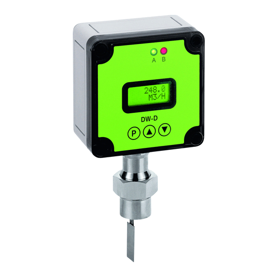
Operation Manual Flow Transmitter DW-D
1.
MOUNTING
1.1
Position of mounting
It is advantageous to install the unit in a straight piece of pipe and to choose a place of
mounting which has the biggest possible distance from elbows, valves etc.
It is especially important to have the biggest possible distance from magnet valves and ball
valves. Please make sure that they are opened as slow as possible, especially if the pipe after
the valve is empty. These measures prevent the measuring system from flow shocks which
can cause damages. We recommend a straight length of 10 d at input side and 5 d at the
output side (d= diameter of pipe).
The apparatus provides a stable signal when installed at closer distances, but depending on
flow conditions it may be less accurate
1.2
Mounting position on electronic view
Please take in consideration that the mounting has to be done EMI conform in order to avoid
interruptions of operations.
Especially the following points have to be attended:
- The provided ferrites have to be mounted as described.
- Signal and supply cable of the DW-D may not directly taken close to 230V or 380V wirings.
- The device should not be installed close to inductance, switching loads, engines or similar
sources of inductive fields.
1.3
Direction of Flow
It is essential that the unit is mounted so that flow is as indicated by the arrow on the body.
The unit will not operate unless installed correctly in this way and the possibility of damage to
the unit cannot be excluded.
1.4
Mounting Orientation
If the display has to be changed to a new position, it is possible to turn it relative to the
housing. To do this, remove the front and back of the housing and remove the screw retaining
the electronic board to the housing. Rotate the electronic board to the new desired position
taking care not to damage the cable link, refit and secure the retaining screws. In a similar
way, the window on the front of the access cover can also be turned.
2.
MOUNTING AT THE TUBE
2.1
Items with THREAD CONNECTION
We recommend sealing all threads with PTFE sealing tape. Ensure no excess of tape is left
protruding into the pipe.
When screwing the unit into a pipe, take care to ensure that the housing is not damaged or
impacted during the process.
2.2
Items with FLANGE CONNECTION
An approved flange seal or gasket must be used. Neither this nor the required fixing bolts are
included in the delivery. Ensure the transmitter is not damaged when tightening the flange
bolts.
©2013 Schmidt
Mess- und Regeltechnik
Fon 0 67 32 - 91 91 20
Fax 0 67 32 - 96 24 42
info@schmidt-messtechnik.de
1
Advertisement
Table of Contents

Subscribe to Our Youtube Channel
Related Manuals for Schmidt DW-D


Summary of Contents for Schmidt DW-D
- Page 1 - The provided ferrites have to be mounted as described. - Signal and supply cable of the DW-D may not directly taken close to 230V or 380V wirings. - The device should not be installed close to inductance, switching loads, engines or similar sources of inductive fields.
- Page 2 Schmidt Mess- und Regeltechnik Operation Manual Flow Transmitter DW-D Items with WELDED SOCKET The welding socket is included in the delivery. Remove by loosening union nut (A). The dimensions shown in the drawing (right) must be adhered to strictly to. Drill a ridge less hole in the pipe.
- Page 3 If you keep the buttons on hold the value is changing continuously. After some time velocity is increasing. At some points of the menu the DW-D informs you which buttons have to be pressed as next step. For example PIN [+/-], ©2013 Schmidt...
- Page 4 RELAIS 1 the red one to RELAIS 2 (B) Adjusting of output occupancy DW-D comes with current, voltage and frequency output. The different output types only can be used alternatively. It is only one pair of connector existing for all functions. Connection is to block KL1 (see point 3.2 , 3.3 and 3.4 respectively drawing of the board).
- Page 5 POWER LOW / PRESS P & respectively PRESS P & . Pressing P and (at same time) DW-D changes back to standard modus. After that the device starts counting from the amount has been present at the time of power failure. This guarantees that the operator is aware of that power supply was interrupted and so the amount indicated perhaps not corresponds to the real quantity.
- Page 6 (Also see point 3.5) Mounting the ferrite The HSW flow transmitter DW-D is EMI certified and comes up to the corresponding norm. The EMI directive will only be achieved, if the provided ferrites are mounted as mentioned under 3.1 3.2 3.33 and 3.4.
- Page 7 Clean the pendulum system before re-installing into the pipe. IMPORTANT! If the DW-D must be separated from the tee loosen nut (A) and cant the unit a little opposed to direction of flow. Then lift the DW-D with pendulum rectangular out of the tee.
Need help?
Do you have a question about the DW-D and is the answer not in the manual?
Questions and answers