Advertisement
Quick Links
Advertisement

Subscribe to Our Youtube Channel
Related Manuals for Cambium Networks Force 110


Summary of Contents for Cambium Networks Force 110
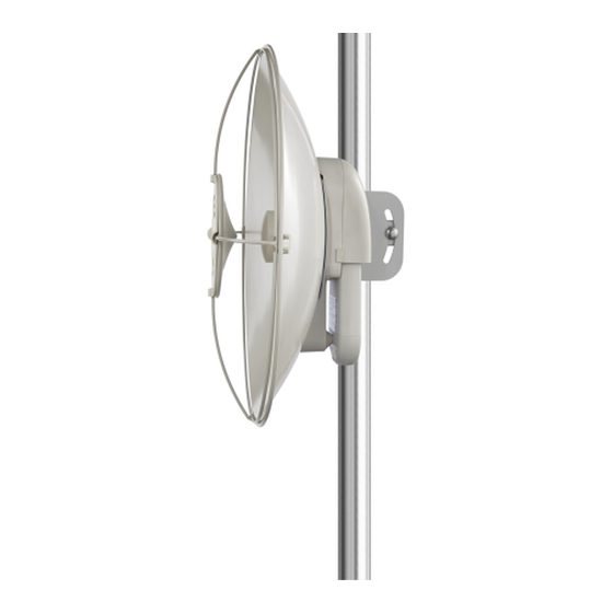
- Page 1 Force 110 Assembly Guide...
- Page 2 Front view showing Step 1 - Align Center feed tube to the dish. Cables go through the dish. The Center feed is used as an alignment tool NOTE: DO NOT PINCH OR BIND THE CABLES. Step 2 – First Align keyway.
- Page 3 Step 3 - Press Center feed to seat on the surface of the Dish. NOTE: DO NOT PINCH OR BIND THE CABLES. NOTE: Make sure that the Center Feed lip is flush with the Dish.
- Page 4 Rear view showing Step 4 - Flip dish and Center feed over. The Center feed assembly to the dish will have press fit and not a slip fit. Figure 1 - Mounting to the Right side of a pole. Figure 2 - Mounting to the Left side of a pole. Step 5 NOTE: DETERMINE THE PROPER POLE ORIENTATION BEFORE FULL ASSEMBLY.
- Page 5 Rear view showing Step 6 Assembly Bottom Housing to dish. Align key way of the Center feed to the Bottom housing. Hold all pieces when flipping over to install screw assembly. Step 7 – 4X: Screw Assembly order: M6 SHCS / Split Washer / Flat Washer (round surface facing down as shown).
- Page 6 Front view showing Step 8 – 4X: Insert screw / spring washer and flat washer to assemble. Finger tight the screws. 4X - 10Nm (8ft-lbs) Step 9 Tighten in a crisscross pattern. Torque to 10.8Nm (8.0 ft lbf)
- Page 7 Step 10 – Push on the Centerfeed firmly until you hear the 4 lock clips engaging (a clipping sound). Step 11 –If the snaps are not fully engaged. Use a flat head screwdriver to engage the snaps.
- Page 9 Step 12 – Assemble the Pole mounting bracket. Flat side of the Carriage bolt is to be installed from the inside of the Bracket (as shown). Insert Carriage bolts - one though square opening and the other though the curved opening. Step 13 –...
- Page 10 Step 14 - Secondary Clip insertion. Do this for all four corners. Ensure that the Clips are facing outwards.
- Page 11 Press firmly on the Retainer Clips when assembling to the dish..
- Page 12 Step 15 - Inserting Secondary Clip Cover. Keep notch facing outward. Do this for all four clips. Step 16 – With the radio pointing up, attach the Cambium Networks Logo Medallion to the Secondary antenna.
- Page 13 Attaching the CSM radio to the Force 110 Step 17 – Gray shielding is H / Black shielding is V Keep cables to the side of the upper radio mount. NOTE: DO NOT PINCH OR BIND THE CABLES. Step 18 - Tighten SMA CONNECTORS.
- Page 14 Step 19 – Keep cable to the left and right of the center support mount. Slide on the ePMP CSM radio. NOTE: DO NOT PINCH OR BIND THE CABLES. Step 20 - Tighten the M5 lock screw to a TORQUE of 6.0 Nm (4.43 ft lbf)
- Page 15 Step 21 – Slide Cover down until you hear a click. ASSEMBLY IS NOW COMPLETE...
- Page 16 ITEM DESCRIPTION BOLT-RHSN_M8X90MM_316SS BOTTOM-HOUSING BRACKET-POLE MOUNT BRACKET, POLE MOUNT, CLAMP BRACKET, POLE MOUNT, RETAINER CENTER FEED 81mm CLIP, RETAINER, COVER CLIP, RETAINER, SUBREFLECTOR COVER-BOTTOM-HOUSING COVER, SUB-REFLECTOR DISH-BRACKET-MOUNT DISH, 450MM FRAME, SUB-REFLECTOR NUT-FLANGE-HEX-LOCKNUT-M8 SCREW, M6x1x14mm, 316SS WASHER, M6 x 6.5mm ID x1.5mm WASHER, SPLIT LOCK, M6 SCREW, SS...
Need help?
Do you have a question about the Force 110 and is the answer not in the manual?
Questions and answers