Advertisement
Solid-state Timer
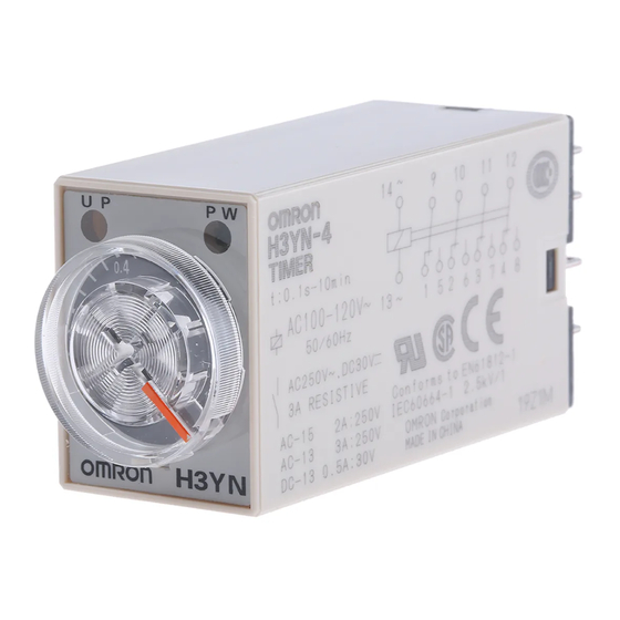
H3YN
Miniature Timer with Multiple Time Ranges
and Multiple Operating Modes
• Minimizes stock.
• Pin configuration compatible with MY Power Relay.
• Standard multiple operating modes and multiple time ranges.
• Conforms to EN61812-1 and IEC60664-1 for Low Voltage, and
EMC Directives.
Model Number Structure
■ Model Number Legend
H3YN-@@-@
1 2
3
1. Output
2: DPDT
4: 4PDT
2. Time Range
None:Short-time range (0.1 s to 10 min)
1: Long-time range (0.1 min to 10 hrs)
Ordering Information
■ List of Models
Supply voltage
24, 100 to 120, 200 to 230 VAC;
12, 24, 48, 100 to 110, 125 VDC
24 VDC
Note: Specify both the model number and supply voltage when ordering.
Example: H3YN-2 24 VAC
■ Accessories (Order Separately)
Connecting Socket
Timer
H3YN-2/-21
PYF08A, PYF08A-N,
PYF08A-E
H3YN-4/-41
PYF14A, PYF14A-N,
H3YN-4-Z/-41-Z
PYF14A-E
Time-limit contact
DPDT
4PDT
4PDT (Twin contacts)
Supply voltage
Track mounting/Front
Connecting Socket
PY08
PY14
3. Contact Type
None:Single contact
Z: Twin contacts
Short-time range model
(0.1 s to 10 min)
H3YN-2
H3YN-4
H3YN-4-Z
Back Connecting Socket
Solder terminal
Wire-wrap terminal
PY08QN(2)
PY14QN(2)
Long-time range model
(0.1 min to 10 h)
H3YN-21
H3YN-41
H3YN-41-Z
PC terminal
PY08-02
PY14-02
H3YN
Solid-state Timer
B-85
Advertisement
Table of Contents

Related Manuals for Omron H3YN


Summary of Contents for Omron H3YN
-
Page 1: Model Number Structure
12, 24, 48, 100 to 110, 125 VDC 4PDT H3YN-4 H3YN-41 24 VDC 4PDT (Twin contacts) H3YN-4-Z H3YN-41-Z Note: Specify both the model number and supply voltage when ordering. Example: H3YN-2 24 VAC Supply voltage ■ Accessories (Order Separately) Connecting Socket Timer Track mounting/Front Back Connecting Socket... -
Page 2: Specifications
Note: 1. Single-phase, full-wave-rectified power supplies can be used. 2. When using the H3YN continuously in any place where the ambient temperature is in a range of 45 C to 50 C, supply 90% to 110% of the rated supply voltages (supply 95% to 110% with 12 VDC type). - Page 3 (3 A at 250 VAC, resistive load at 1,800 operations/h) (see note 2) Impulse withstand voltage Between power terminals: 3 kV for 100 to 120 VAC, 200 to 230 VAC, 100 to 110 VDC, 125 VDC 1 kV for 12 VDC, 24 VDC, 48 VDC, 24 VAC Between exposed non-current-carrying metal parts: 4.5 kV for 100 to 120 VAC, 200 to 230 VAC, 100 to 110 VDC, 125 VDC...
- Page 4 Load current (A) Load current (A) Reference: A maximum current of 0.6 A can be switched at 125 VDC (cos = 1). Maximum current of 0.2 A can be switched if L/R is 7 ms. In both cases, a life of 100,000 operations can be expected.
-
Page 5: Pulse Operation
UP PW UP PW Pulse Operation A pulse output for a certain period can be obtained with a random external input signal. Use the H3YN in interval mode as shown in the following timing charts. H3YN-2/-21 Power (9-14) External short circuit... -
Page 6: Operation
Timing chart H3YN-2/-21 H3YN-4/-41 ON-delay Power (13-14) Power (13-14) Power Time limit contact Time limit contact NC (9-1, 10-2, 11-3, NC (9-1, 12-4) 12-4) Output Time limit contact Time limit contact NO (9-5, 12-8) NO (9-5, 10-6, 11-7, 12-8) Run/Power indicator... -
Page 7: Time Ranges
■ DIP Switch Settings The 1-s range and ON-delay mode for H3YN-2/-4/-4-Z, the 1-min range and ON-delay mode for H3YN-21/-41/-41-Z are factory-set before shipping. Time Ranges Model Time range Time setting Setting Factory-set range H3YN-2, 0.1 to 1 s H3YN-4... - Page 8 PY08 (PY14 (see note)) PY08QN (PY14QN (see note)) PYF08A/PYF08A-N/PYF08A-E (PYF14A/PYF14A-N/PYF14A-E (see note)) H3YN H3YN H3YN Series Series Series PY08QN (PY14QN) PY08 (PY14) PYF08A (PYF14A) Note: Models in parentheses are Connecting Sockets to the H3YN-4/-41 or H3YN-4-Z/-41-Z. H3YN B-92 Solid-state Timer...
-
Page 9: Connecting Sockets
■ Accessories (Order Separately) Connecting Sockets Use the PYF@A, PY@, PY@-02, or PY@QN(2) to mount the H3YN. When ordering any one of these Sockets, replace “@” with “08” or “14.” Track Mounting/Front Connecting Sockets PYF08A Terminal Arrangement Mounting Holes Two, 4.2... - Page 10 29.5 max. 1 x 1 41.5 max. (see note) PY08QN PY14QN PY08QN(2) PY14QN(2) Note: With PY@QN(2)(-3), dimension * should read 20 max. and dimension ** 36.5 max. PY08-02, PY14-02 Terminal Arrangement (Bottom View) 22 max. 29.5 25.5 max. max. 16.5 max.
- Page 11 Socket Mounting Plates The PYP-1 is a Socket Mounting Plate for a single Socket and the PYP-18 is a Socket Mounting Plate for 18 Sockets. The PYP-18 can be cut appropriately according to the number of Sockets to be used.
- Page 12 H3YN-4/-41 or H3YN-4-Z/-41-Z, connect the Unit so that output con- 45 C to 50 C. Supply 90% to 110% of the rated voltages (at 12 VDC: tacts (contacts of different poles) have the same electric potential.
Need help?
Do you have a question about the H3YN and is the answer not in the manual?
Questions and answers