
Related Manuals for Ihse 474-SNMP


Summary of Contents for Ihse 474-SNMP
- Page 1 USER MANUAL SNMP Module 474-SNMP / 474-SNMPV3 Dokument 474-SNMP-Rev02.00_en Firmware version: 1.02 Edition: 2021-02-08 Software version: 4.0.0.0...
- Page 2 Product Identification The model and serial number of your products are indicated on the bottom of our products. Always refer to this information when you need to contact your dealer or the support of IHSE GmbH (see chapter 10, page 101).
-
Page 3: Table Of Contents
3.8.2 6-Slot Chassis Draco vario 474-BODY6BPF ..............17 3.8.3 21-Slot Chassis Draco vario 474-BODY21/4U ..............17 Device Views SNMP Modules ......................18 3.9.1 Module 474-SNMP ......................18 3.9.2 Module 474-SNMPv3......................18 3.10 Status Indication of the Chassis ......................19 3.10.1 6-Slot Chassis Draco vario 474-BODY6BP ................ - Page 4 Table of Contents SNMP Module Setting up Network and Firewall Releases ..................27 Installing the SNMP Module ....................... 27 Installing Management Software ......................28 4.3.1 Connecting SNMP Module to the Computer ..............29 4.3.2 Starting Management Software ..................29 4.3.3 Connecting Management Software with the SNMP Module ..........
- Page 5 MTBF ..............................97 Maintenance ..............................97 Troubleshooting ............................98 SNMP Module ............................ 98 No Access to the SNMP Modul ......................99 9.2.1 474-SNMP Setting Jumper ....................99 9.2.2 474-SNMPV3 Setting Jumper ..................100 Technical Support ............................101 10.1 Support Checklist ..........................101 10.2...
- Page 6 Table of Contents SNMP Module EU Declaration of Conformity ........................103 Glossary ..............................104 Table of Figures ............................105...
-
Page 7: Important Information
SNMP Module Important Information Important Information Symbols for Warnings and Helpful Information The meaning of the symbols used for warnings and helpful information in this manual is described below: CAUTION CAUTION, used with the safety alert symbol, indicates a hazardous situation which, if not avoided, could result in minor or moderate injury. -
Page 8: Eu Declaration Of Conformity
Important Information SNMP Module EU Declaration of Conformity For information about the Declaration of Conformity refer to chapter 12, page 103. A copy of the original, product-specific EU Declaration of Conformity can be provided upon request. For contact details, see page 2 of this manual. -
Page 9: Safety Instructions
SNMP Module Safety instructions Safety instructions To ensure reliable and safe long-term operation of your device, please note the following guidelines: Read this user manual carefully. Only use the device according to this user manual. Failure to follow the instructions described can damage the device or endanger the security of your data. - Page 10 Safety instructions SNMP Module Disconnect the Device from the Circuit NOTICE The cable plugs on the device side can contain a lock. In the event of a necessary quick and complete disconnection from external electric circuits: remove all corresponding cable plugs from the socket, ...
-
Page 11: Description
The Draco tera-Tool (management software) is available as a single executable program file (desktop and app version) that does not require a separate installation. The management software can be downloaded from the link https://www.ihse.de/software. Advanced settings can be configured on the KVM extender operating system using the management software: •... -
Page 12: System Overview
Description SNMP Module System Overview 3.3.1 KVM Extender - Structure A pair of KVM Extenders consists of 2 KVM Extenders, each with at least one CPU extender module and at least one CON extender module. The various extender modules are installed respectively in a Draco vario chassis (2-slot, 4-slot or 6-slot) on the CPU side (CPU Unit) and console side (CON Unit). -
Page 13: Installation Example
SNMP Module Description 3.3.3 Installation Example With an SNMP module those extenders are monitored that were installed in the same chassis as the SNMP module. In this example the extenders of the CPU Unit are monitored. The CPU Unit is connected directly to the source (computer, CPU) using the supplied cables. The CON Unit is connected to the console (monitor, keyboard, and mouse). -
Page 14: Product Types
Wall-/Tablemount L-Brackets for all 2-/4-/6-Slot chassis 474-PSU21 Spare PSU for 21-slot chassis, slide-in, hot-swap 474-BLND1 Blanking plate with IHSE Logo, 1-Slot for Draco vario chassis 474-6FAN Optional fan for Draco vario 6-slot chassis with backplane Accessories Cables and Power Supply Units... -
Page 15: Scope Of Delivery
SNMP Module Description Scope of Delivery Depending on the order, the scope of delivery contains the following items: Product type Scope of delivery 474-SNMP 1x Module 474-SNMP • 1x Serial control cable • 474-SNMPV3 1x Module 474-SNMPV3 • 474-BODY6BP 474-BODY6BPF 2x country-specific power cord per chassis •... -
Page 16: Device Views Draco Vario Chassis
Description SNMP Module Device Views Draco vario Chassis NOTICE Exceeding the maximum permissible power consumption In addition to the power consumption of the extender and add-on modules, the power consumption of the connected peripherals must be added. Note the maximum power consumption of the chassis (see chapter 7.3.1, page 96). 3.8.1 6-Slot Chassis Draco vario 474-BODY6BP Fig. -
Page 17: 6-Slot Chassis Draco Vario 474-Body6Bpf
SNMP Module Description 3.8.2 6-Slot Chassis Draco vario 474-BODY6BPF Fig. 8 Interface side chassis 474-BODY6BPF Slot 1 Slot 5 Slot 2 Slot 6 Slot 3 Power supply AC (standard) Slot 4 Power supply AC (redundancy, optional) 3.8.3 21-Slot Chassis Draco vario 474-BODY21/4U Fig. -
Page 18: Device Views Snmp Modules
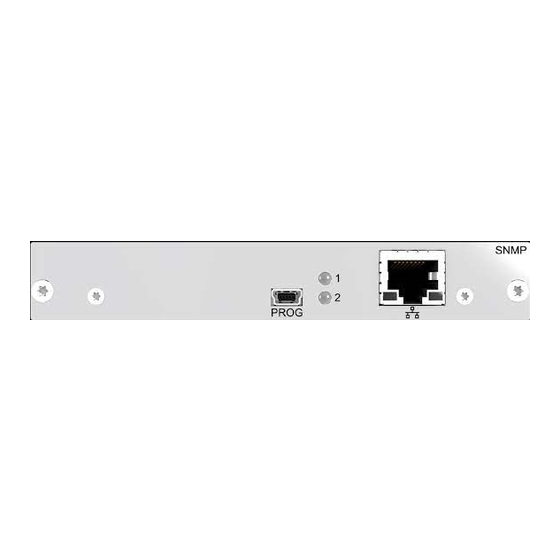
Slot 5: 474-BODY6BP and 474BODY6BPF (with a production date of the chassis later than March 2014) Slot 21: 474-BODY21/4U 3.9.1 Module 474-SNMP Fig. 11 Interface side 474-SNMP RS232 serial (D-Sub 9, female socket) Input / Output RJ45 (network connection) This module works with the unencrypted SNMPv1 standard. 3.9.2 Module 474-SNMPv3 Fig. -
Page 19: Status Indication Of The Chassis
SNMP Module Description 3.10 Status Indication of the Chassis The Draco vario chassis are equipped with LEDs for status information. 3.10.1 6-Slot Chassis Draco vario 474-BODY6BP Fig. 13 Interface side chassis 474-BODY6BP - status LEDs Status LED for power supply 1 Status LED for power supply 2 Status LEDs for Power Supply Voltage Pos. -
Page 20: 3.10.3 21-Slot Chassis Draco Vario 474-Body21/4U
Description SNMP Module 3.10.3 21-Slot Chassis Draco vario 474-BODY21/4U Fig. 15 Rear view chassis 474-BODY21/4U - status LEDs Status LED for power supply (redundancy) Status LED for power supply (standard) Fault LED for power supply (redundancy) Fault LED for power supply (standard) Status LEDs for Power Supply Voltage Pos. -
Page 21: Status Indication Of The Snmp Modules
Description 3.11 Status Indication of the SNMP Modules 3.11.1 Module 474-SNMP Fig. 16 Interface side module 474-SNMP - status LEDs Status LED 1 SNMP module Link status LED network connection Activity status LED network connection Status LED 2 SNMP module Status LEDs of the SNMP module Pos. -
Page 22: 3.11.2 Module 474-Snmpv3
Description SNMP Module 3.11.2 Module 474-SNMPV3 Fig. 17 Interface side module 474-SNMPV3 - status LEDs Status LED 1 SNMP module Status LED 2 SNMP module Link status LED network connection Activity status LED network connection Status LEDs of the SNMP module Pos. -
Page 23: Control Options Via Management Software
SNMP Module Description 3.12 Control Options via Management Software 3.12.1 Management Software Menu Structure The menu structure of the management software is subdivided into various sections: Management software menu structure Fig. 18 Menu bar (top line) Task area (left menu section) Toolbar (second line) Working area (right menu section) Tab bar (third line) -
Page 24: 3.12.2 Management Software Toolbar
Description SNMP Module Information for operating and for support functions The operation of the management software is intuitive and corresponds to the user interface of common operating systems. Help texts: • The management software contains its own support function. The integrated help texts in the working area of the management software can be activated or deactivated by the checkbox in the upper right corner. -
Page 25: 3.12.4 Management Software Keyboard Control
SNMP Module Description 3.12.4 Management Software Keyboard Control The following keyboard commands are available for the navigation and configuration within the menus: Keyboard command Function <Cursor Left> Cursor to the left <Cursor Right> Cursor to the right <Cursor Up> Line up <Cursor Down>... -
Page 26: 3.12.7 Management Software Sort Function
Description SNMP Module 3.12.7 Management Software Sort Function Lists and tables in the management software offer a sorting function for fast and smooth search. An active filter is indicated by an arrow in the header. Sort function Action Result Ascending sort Click with the primary mouse button The column is sorted in ascending •... -
Page 27: Installation
SNMP Module Installation Installation NOTICE Please verify that interconnect cables, interfaces, and handling of the devices comply with the requirements (see chapter 7, page 94). First-time users are recommended to set up the system in a test environment that is limited to a single room. -
Page 28: Installing Management Software
On Windows operating systems, the portable management tool Specification Java TeraToolApp requires no Java installation. Management software Draco tera- Downloaded from https://www.ihse.de/software APP version Tool Network connection Available between computer and SNMP module Installing the management software The management software is available as a single executable program file that does not require a separate installation. -
Page 29: Connecting Snmp Module To The Computer
SNMP Module Installation 4.3.1 Connecting SNMP Module to the Computer NOTICE For a connection between computer and SNMP module via switch or hub, parallel assembled network cables are required. Use only a network connection between computer and the SNMP module that is not primarily used for streaming audio or video data ... -
Page 30: Connecting Management Software With The Snmp Module
2. Enter the IP address according to the network configuration of the SNMP module (see chapter 5.4.2, page 38). Default Settings of the SNMP module: 474-SNMP: IP-Address 192.168.100.99 and DHCP is deactivated. 474-SNMPV3: IP-Address 192.168.100.99 and DHCP is activated. 3. Enter the username and password of the administrator (see chapter 5.5, page 50). -
Page 31: Configuration Via Management Software
SNMP Module Configuration via Management Software Configuration via Management Software NOTICE Possible loss of changes By clicking the Apply button changes are applied to the active configuration and saved in the volatile memory of the SNMP module. In the event of a sudden power failure, these changes are lost. To save changes permanently: ... -
Page 32: Configuring In Offline Mode
Configuration via Management Software SNMP Module Configuring in Offline Mode Configuration and system settings via management software can be changed in offline mode without a direct connection between SNMP module and management software. Afterwards, the configuration must be uploaded to the SNMP module. Hereby, the following steps are necessary: 1. -
Page 33: Setting Management Software Options
SNMP Module Configuration via Management Software Setting Management Software Options The settings of the management software can be customized and optimized to support you configure your SNMP module. The settings can be set in the offline mode. A restart is required to activate changes in the options menu. 5.3.1 Setting Program Default Settings To avoid the repeated entry of data in the management software, this data can be saved in the default... -
Page 34: Setting Font Size And Tooltip In The Toolbar
Configuration via Management Software SNMP Module To activate or set the default settings, proceed as follows: 1. Select Extras > Options in the menu bar. The Options menu opens and shows the Default Settings tab. 2. Enter the appropriate data. 3. -
Page 35: Setting Language Of The Management Software
SNMP Module Configuration via Management Software 5.3.3 Setting Language of the Management Software The language within the management software is set in this menu. The charset must match the selected language to ensure correct representation. 1. Select Extras > Options in the menu bar and open the Language tab. 2. -
Page 36: Setting Autostart Of The Device Finder
Configuration via Management Software SNMP Module 5.3.4 Setting Autostart of the Device Finder To start the device finder automatically when starting the management software, proceed as follows: 1. Select Extras > Options in the menu bar and open the Miscellaneous tab. 2. -
Page 37: System Settings
SNMP Module Configuration via Management Software System Settings After changing the IP address, the new IP address is required to connect to the management software after restart. 5.4.1 Defining the SNMP Module The parameters for the SNMP module are defined in this menu. Management software menu System Settings - System Fig. -
Page 38: Setting The Network Configuration
Configuration via Management Software SNMP Module 5.4.2 Setting the Network Configuration The parameters for the network configuration are set in this menu. NOTICE A change in system-relevant parameters (e.g. change of the IP address) is immediately displayed in the management software. To initialize system-relevant configuration changes on the SNMP module, the SNMP module must be restarted. - Page 39 SNMP Module Configuration via Management Software Multicast Field Entry Description Multicast Byte Input of the multicast address, if using within a multicast group (default is: 255.255.255.255 (broadcast)) Network Services Field Entry Description API Service Activated LAN interface at the SNMP module activated for access via management software (API service port 5555) SSL Support Activated...
-
Page 40: Setting The Syslog Function
Configuration via Management Software SNMP Module 5.4.3 Setting the Syslog Function The parameters for the syslog function are set in this menu. NOTICE A change in system-relevant parameters (e.g. change of the Syslog server) is immediately displayed in the management software. To initialize system-relevant configuration changes on the SNMP module, the SNMP module must be restarted. - Page 41 SNMP Module Configuration via Management Software To set parameters for the syslog function, proceed as follows: 1. Select System Settings > Network in the task area. 2. Click the Activate Edit Mode menu item in the toolbar. 3. Select the Syslog tab in the working area. 4.
- Page 42 Configuration via Management Software SNMP Module Option Description Maximum Number of Allowed maximum number of log files Log Files Acoustic Notification Enables acoustic notification for errors Autostart When starting the management software, the syslog function will be started in the background Open Monitoring Tab When starting the management software, the monitoring tab will be opened When reaching the maximum log file size, a new log file will be created.
-
Page 43: Setting The Snmp Function
SNMP Module Configuration via Management Software 5.4.4 Setting the SNMP Function The SNMP function allows all function-critical and safety-critical elements of the SNMP module to be monitored and queried. This function complies with the RFC 1157 conformal standard. Two SNMP servers can be used at the same time. - Page 44 Configuration via Management Software SNMP Module The following parameters are pre-configured or can be configured: SNMP Agent Field Entry Description SNMP Agent Activated (not Permission for an active query of the SNMP agent for traps is deactivate- granted. This activation is a prerequisite for using the SNMP able) server.
- Page 45 SNMP Module Configuration via Management Software Activating the SNMP Monitoring To activate the SNMP monitoring, proceed as follows: 1. Select System Settings > Network in the task area. 2. Select the SNMP tab in the working area. 3. Click the Activate Edit Mode menu item in the toolbar. 4.
- Page 46 Configuration via Management Software SNMP Module To set or activate the presetting, proceed as follows: 1. Select Extras > Options in the menu bar and open the SNMP tab. 2. Modify the desired settings. 3. Click the Ok button to confirm your entries. 4.
- Page 47 SNMP Module Configuration via Management Software Creating an SNMPv3 User for the SNMP Server In the following menu, the login data for an SNMPv3 user can be set up for the computer on which the management software is operated (SNMP server). The SNMP server authenticates itself with the agent using this login data.
- Page 48 Configuration via Management Software SNMP Module The following parameters are required to create a new SNMPv3 user on the SNMP server: Option Description Username SNMPv3 username, not changeable (default: snmp) Authentication Only SHA protocol, no selection available Protocol Authentication Authentication password for the SNMPv3 user (case sensitive, input of minimum Password 8 characters up to 16 characters) Privacy Protocol...
-
Page 49: Setting The Date And Time
SNMP Module Configuration via Management Software 5.4.5 Setting the Date and Time The parameters for the system configuration are set in this menu, based on Simple Network Time Protocol (SNTP): Fig. 33 Management software menu System Settings - Date and Time The following parameters are pre-configured or can be configured: SNTP Field... -
Page 50: User Settings
Configuration via Management Software SNMP Module Configuring the time server To configure a time server, proceed as follows: 1. Select System Settings > Date and Time in the task area. 2. Click the Activate Edit Mode menu item in the toolbar. 3. - Page 51 SNMP Module Configuration via Management Software Administrator The administrator (username: admin) has the permission to configure the system. The following parameters can be configured for the administrator: Field Entry Description Full Name Text Optional: personal username (case sensitive, up to 32 characters) Password / New Text...
-
Page 52: Extender Settings
Configuration via Management Software SNMP Module Extender Settings The SNMP module recognizes the physical link of extenders and add-on modules and queries their data, which is displayed and managed in this menu as extender units. An add-on module is not created as an independent extender unit. -
Page 53: Extender Type
SNMP Module Configuration via Management Software 5.6.1 Extender Type To display extender types, proceed as follows: 1. Select Extender & Devices > EXT Units in the task area. 2. Click the extender unit to be displayed. The extender type is displayed on the right side of the working area. The Basic column stands for the extender of the selected extender unit. -
Page 54: Firmware Version
Configuration via Management Software SNMP Module 5.6.2 Firmware Version To display extender unit information or to modify settings, proceed as follows: 1. Select Extender & Devices > EXT Units in the task area. 2. Click the Activate Edit Mode menu item in the toolbar. 3. -
Page 55: Parameters
SNMP Module Configuration via Management Software 5.6.3 Parameters To display parameters of the extender units, proceed as follows: 1. Select Extender & Devices > EXT Units in the task area. 2. Click the Activate Edit Mode menu item in the toolbar. 3. - Page 56 Configuration via Management Software SNMP Module The parameters of the extender unit are displayed on the right side of the working area. Management software menu Extender & Devices - EXT Units - displayed parameters Fig. 39 The following functions are available: Button Function Open…...
- Page 57 SNMP Module Configuration via Management Software Modifying Parameters To modify parameters of an extender unit, proceed as follows: 1. Read the extender unit parameters (see chapter 5.6.3, page 55). 2. Modify the parameters. 3. Click the Transmit button. A query for transmission appears. 4.
-
Page 58: Fig. 41 Management Software Menu Extender & Devices - Ext Units - Select Extender Units
Configuration via Management Software SNMP Module Assigning Parameter To assign parameters of an extender unit to another extender unit, proceed as follows 1. Select Extender & Devices > EXT Units in the task area. 2. Click the Activate Edit Mode menu item in the toolbar. 3. -
Page 59: Fig. 42 Management Software Menu Extender & Devices - Ext Units
SNMP Module Configuration via Management Software 11. Click the Confirm to continue checkbox to confirm the start of the assignment. 12. Click the Next button to start of the assignment. Fig. 42 Management software menu Extender & Devices - EXT Units - start parameter assignment The progress of the parameter assignment is displayed. -
Page 60: Usb-Hid Ghosting
Configuration via Management Software SNMP Module 5.6.4 USB-HID Ghosting To display the USB-HID ghosting of extender units, proceed as follows: 1. Select Extender & Devices > EXT Units in the task area. 2. Click the Activate Edit Mode menu item in the toolbar. 3. -
Page 61: Edid
SNMP Module Configuration via Management Software 5.6.5 EDID To display the active monitor EDID in the extender unit, proceed as follows: 1. Select Extender & Devices > EXT Units in the task area. 2. Click the Activate Edit Mode menu item in the toolbar. 3. -
Page 62: Saving Configuration
Configuration via Management Software SNMP Module Saving Configuration NOTICE By default, the last configuration that has been saved in the permanent SNMP module memory will be restored after a restart of the SNMP module. When starting the SNMP module for the first time, the factory configuration will be copied into the current configuration. -
Page 63: Saving The Configuration Locally
SNMP Module Configuration via Management Software 5.7.2 Saving the Configuration Locally Configurations can be saved as a file that can be stored independently from the SNMP module. To save a configuration file locally, proceed as follows: 1. Select File > Save or File > Save As in the menu bar. 2. -
Page 64: Opening A Locally Saved Configuration
Configuration via Management Software SNMP Module Opening a Locally Saved Configuration To open a locally saved configuration, proceed as follows: 1. Click the Open… menu item in the toolbar. 2. Navigate to the location of the configuration file to be opened. 3. -
Page 65: Uploading A Configuration To The Snmp Module
SNMP Module Configuration via Management Software Uploading a Configuration to the SNMP Module Using the function Upload, the created configuration can be saved in a storage location in the SNMP module (default). However, it does not replace the buffering of an active configuration (see chapter 5.7.1, page 62). -
Page 66: Fig. 50 Management Software Menu Upload - Select Configuration Slot
Configuration via Management Software SNMP Module 7. Click the Finish button to save the configuration into the selected storage location. Fig. 50 Management software menu Upload - Select Configuration Slot... -
Page 67: Activating A Predefined Configuration
SNMP Module Configuration via Management Software 5.10 Activating a Predefined Configuration To activate an uploaded configuration, proceed as follows: 1. Select Status & Updates > Activate Configuration in the task area. 2. Select the configuration to be activated. 3. Click the Activate button to activate the selected configuration. A query to restart the SNMP module appears. -
Page 68: Downloading A Configuration From The Snmp Module
Configuration via Management Software SNMP Module 5.11 Downloading a Configuration from the SNMP module Configurations saved in the SNMP module can be downloaded for offline editing in this menu. To download a configuration from the SNMP module, proceed as follows: 1. -
Page 69: Operation
SNMP Module Operation Operation System Check The system check offers a diagnostic function for checking the device configuration. The feature indicates non-optimal as well as incorrect settings and displays issues instructions. The system check is only used to check plausibility and does not make any active configuration changes. The following configuration parts are checked: •... -
Page 70: Fig. 55 Management Software Report System Check
Operation SNMP Module Fig. 55 Management software report System Check... -
Page 71: Device Finder
SNMP Module Operation Device Finder The Device Finder offers the possibility to find all SNMP boards that are located in the same subnetwork. This is useful, for example, if the IP address of a specific SNMP board is unknown and should be accessed via IP. -
Page 72: Network Check
Operation SNMP Module Network Check The network check checks the firewall settings for the ports available in the network. NOTICE Available ports are shown in green. If a port is not available, the corresponding entry appears in red and instructions are displayed. To start the network check, proceed as follows: 1. -
Page 73: Status Query Via Management Software
SNMP Module Operation Status Query via Management Software 6.4.1 Device Status The device configuration and the connections to the SNMP module are displayed in this menu. Select View > SNMP in the task area to display the current connections. Fig. -
Page 74: Network Status
Operation SNMP Module 6.4.2 Network Status The current network connection is displayed in this menu. Select System Settings > Network in the task area to query the network configuration. Fig. 60 Management software menu System Settings - Network - General For information about the parameters, please see chapter 5.4.2, page 38. -
Page 75: Snmp Firmware Status
SNMP Module Operation 6.4.3 SNMP Firmware Status The firmware status of the SNMP module is displayed in this menu. Select Status & Updates > Status - SNMP Firmware in the task area to query the current firmware status of the SNMP module. Management software menu Status &... -
Page 76: Extender Firmware Status
Operation SNMP Module 6.4.4 Extender Firmware Status The firmware status of the extenders is displayed in this menu. Select Status & Updates > Status - Extender Firmware in the task area to query the current firmware status of the extenders. Fig. -
Page 77: Syslog Monitoring
SNMP Module Operation 6.4.5 Syslog Monitoring The syslog function offers a complete logging of the SNMP module, the extenders and the chassis for activities, warnings, and error messages. During logging all events are written continuously into log files and stored locally. NOTICE Syslog messages are transmitted via UDP. - Page 78 Operation SNMP Module Filter function To filter relevant messages from the multitude of logged activities of the SNMP module, the extenders and the chassis, the syslog monitoring offers various filter options. To set and activate a filter, proceed as follows: 1.
-
Page 79: Fig. 64 Management Software Menu Monitoring - Syslog - Example For Search Result
SNMP Module Operation Search function The search function can be used to search for specific Syslog messages from a variety of logged activities and relevant messages from the SNMP module, extenders, and chassis. Fig. 64 Management software menu Monitoring - Syslog - example for search result To find specific syslog messages, proceed as follows: 1. -
Page 80: Snmp-Monitoring
Operation SNMP Module 6.4.6 SNMP-Monitoring The SNMP function allows all function-critical and safety-critical elements of the SNMP module, the extenders, and the chassis to be monitored and queried. This function complies with the RFC 1157 conformal standard. NOTICE When using SNMP monitoring, for reasons of access security, the use of a dedicated network according to the IT-Grundschutz catalog is recommended. - Page 81 SNMP Module Operation Filter function To filter relevant messages from the multitude of logged activities of the SNMP module, the extenders and the chassis, the SNMP monitoring offers various filter options. To set and activate a filter, proceed as follows: 1.
-
Page 82: Fig. 66 Management Software Menu Monitoring - Snmp - Example For Search Result
Operation SNMP Module Search function The search function can be used to search for specific SNMP messages from a variety of logged activities and relevant messages from the SNMP module, extenders, and chassis. Fig. 66 Management software menu Monitoring - SNMP - example for search result To find specific syslog messages, proceed as follows: 1. -
Page 83: Saving The Status Via Management Software
SNMP Module Operation Saving the Status via Management Software 1. Click the Save Status menu item in the toolbar to read out the overall status of the device and store it locally (file extension .zip). A dialog appears. 2. Navigate to the directory you want to save the status file 3. -
Page 84: Fig. 69 Management Software Menu Save Status - Save Ext Unit Settings
Operation SNMP Module 6. Click the Save EXT Units Settings checkbox to save your extender settings. 7. Click the Next button. Fig. 69 Management software menu Save Status - Save EXT Unit Settings 8. Wait until all steps show green checkmarks and the “Saving status successful” message is displayed. -
Page 85: Opening The Locally Saved Status In The Management Software
SNMP Module Operation Opening the Locally Saved Status in the Management Software To load a locally saved status, proceed as follows: 1. Select Device > Load Status… in the menu bar. 2. Navigate to the storage location of the status file to be opened. 3. -
Page 86: Status Query In An External Snmp Software
Operation SNMP Module Status Query in an external SNMP Software Using an external SNMP software, further information about the SNMP module is available, e.g. ID, configuration, version, or status. Module status Available Ready Service mode No link status Invalid Power supply status No power supply available Not available Temperatuer status... -
Page 87: Updating The Firmware
SNMP Module Operation Updating the Firmware 6.8.1 Updating the SNMP Firmware via Management Software NOTICE To process successful firmware updates and avoid failures: Only use computers to update the SNMP module that are not integrated into the SNMP module setup, ... -
Page 88: Fig. 73 Management Software Dialog Save Device Status
Operation SNMP Module Preparation If the syslog function has not been set yet, we recommend activating the syslog function (see chapter 5.4.3, page 40) before updating the firmware to log the update in case of update errors. To be prepared for a firmware update, proceed as follows: 1. -
Page 89: Updating The Extender Firmware Via Management Software
The firmware of the SNMP module can be updated in this menu, except the firmware type MSD. For special function extensions, it may be necessary to update the firmware type MSD. This is usually done on the instruction of IHSE Tech Support. Fig. 75 Management software menu Status &... - Page 90 Operation SNMP Module The different modules can be expanded and collapsed by left-clicking on the “plus” and “minus” symbols in the Name column. By clicking on the “plus” and “minus” symbol in the upper right corner of the working area, you can expand and collapse all module information with a click of the primary mouse button.
-
Page 91: Powering Down And Resetting Via Management Software
SNMP Module Operation Powering Down and Resetting via Management Software 6.9.1 Powering Down the SNMP Module NOTICE After shutting down, the SNMP module can be disconnected from the power supply. To shut down the SNMP module, proceed as follows: 1. Select Device > Advanced Service > Shut down SNMP Board in the menu bar. An access window appears. -
Page 92: Restarting The Snmp Module
Operation SNMP Module 6.9.2 Restarting the SNMP Module NOTICE When restarting the SNMP module, the current configuration is saved in the permanent memory of the SNMP module and the SNMP module will be restarted with the active configuration. To perform a restart of the SNMP module, proceed as follows: 1. -
Page 93: Resetting The Snmp Module To The Factory Settings
4. Click the Yes button to reset the device. Management software dialog Factory Reset SNMP Board Fig. 81 The SNMP module is reset to factory settings and DHCP is activated (474-SNMPV3) or deactivated (474-SNMP). Fig. 82 Management software message Factory Reset (example 474-SNMPV3) -
Page 94: Technical Data
Technical Data SNMP Module Technical Data Interfaces 7.1.1 Mini-USB This interface enables a customer specified communication with the SNMP module. The firmware could also be updated using this interface. 7.1.2 RJ45 (Network) The network communication of the devices requires a 100BASE-T connection. The cabling has to be done according to EIA/TIA-568-B (100BASE-T) with RJ45 connectors at both ends. -
Page 95: Connector Pinouts
SNMP Module Technical Data Connector Pinouts 7.2.1 Mini-USB, Type B Connector Signal Color +5 V (DC) Data - White Data + Green Not connected Black 7.2.2 RJ45 (Netzwerk) Connector Signal Signal Not connected Not connected Not connected Not connected 7.2.3 D-Sub 9 (Serial) RS232 Connector Signal... -
Page 96: Power Supply, Current Draw And Power Consumption
In addition to the current draw of the extender and additional modules, there is also the current draw of the connected peripherals. Note the maximum current draw of the housing (see chapter 7.3.1, page 96). Product type Maximum current draw Maximum power consumption 474-SNMP 300 mA 1,4 W 474-SNMPV3 510 mA 2,4 W... -
Page 97: Weight
SNMP Module Maintenance Module Dimension 474-SNMP 129 x 20 x 145 mm (5.1" x 0.8" x 5.7") 474-SNMPV3 129 x 20 x 145 mm (5.1" x 0.8" x 5.7") Weight The following table contains the weight when the respective chassis is fully equipped, for both the CPU Unit and the CON Unit. -
Page 98: Troubleshooting
Troubleshooting SNMP Module Troubleshooting SNMP Module Fig. 83 Interface side SNMP modules - failure indication Diagnosis Possible reason Measure LED 1 or LED 2 off No computer connected Connect the computer. Check the network cable. Check the connectors. No network connection No connection between ... -
Page 99: No Access To The Snmp Modul
5. Switch off the SNMP module / disconnect from power supply. 6. Remove the jumper. 7. Switch on the SNMP module. The SNMP module has been reset to factory settings, incl. administrator password and network configuration. Fig. 84 474-SNMP - setting of jumper 3 SNMP module 474-SNMP Jumper 3... -
Page 100: 474-Snmpv3 Setting Jumper
Troubleshooting SNMP Module 9.2.2 474-SNMPV3 Setting Jumper 1. Switch off the SNMP module / disconnect from power supply. 2. Set jumper 2. 3. Switch on the SNMP module. 4. Wait 2 minutes. 5. Switch off the SNMP module / disconnect from power supply. 6. -
Page 101: Technical Support
SNMP Module Technical Support Technical Support Prior to contacting support please ensure you have read this manual, and then installed and set-up your KVM Extender as recommended. 10.1 Support Checklist To efficiently handle your request, it is necessary that you complete a support request checklist (Download). -
Page 102: Certificates/Directives
Certificates/Directives SNMP Module Certificates/Directives 11.1 North American Regulatory Compliance This equipment has been found to comply with the limits for a Class A digital device, pursuant to Part 15 of the FCC Rules. These limits are designed to provide reasonable protection against harmful interference when the equipment is operated in a commercial environment. - Page 103 Benzstraße 1 88094 Oberteuringen Germany Product Type SNMP Module Product number 474-SNMP and 474-SNMPV3 2014/30/EU Council Directive on the approximation of the laws of the Member States relating to electromagnetic compatibility. 2014/35/EU Council Directive on the harmonization of the laws of the Member States relating to the making available on the market of electrical equipment designed for use within certain voltage limits.
- Page 104 Glossary SNMP Module Glossary The following terms are commonly used in this manual or in video and KVM technology. Term Description CON Unit Component of a KVM Extender or Media Extender to connect to the console (monitor(s), keyboard and mouse; optionally also with USB 2.0 devices) CPU Unit Component of a KVM Extender or Media Extender to connect to a source (computer, CPU)
- Page 105 Interface side chassis 474-BODY6BPF - status LEDs ..............19 Fig. 15 Rear view chassis 474-BODY21/4U - status LEDs ..............20 Fig. 16 Interface side module 474-SNMP - status LEDs ................21 Fig. 17 Interface side module 474-SNMPV3 - status LEDs ..............22 Fig. 18 Management software menu structure ..................
- Page 106 Table of Figures SNMP Module Fig. 41 Management software menu Extender & Devices - EXT Units - select extender units ..58 Fig. 42 Management software menu Extender & Devices - EXT Units - start parameter assignment ....................... 59 Fig. 43 Management software menu Extender &...
- Page 107 SNMP Module Table of Figures Fig. 83 Interface side SNMP modules - failure indication ................. 98 Fig. 84 474-SNMP - setting of jumper 3 ....................99...
Need help?
Do you have a question about the 474-SNMP and is the answer not in the manual?
Questions and answers