Table of Contents
Advertisement
Quick Links
Advertisement
Table of Contents

Related Manuals for Socket & See FFCB 100


Summary of Contents for Socket & See FFCB 100
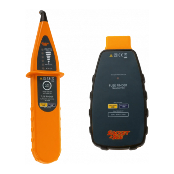
- Page 1 FFCB 100 Easy Fuse Finder Instruction Manual & Specification SS0015V2...
- Page 2 SS0015V2 1. Safety 1.1 Equipment Markings Caution - refer to the instruction manual Construction is double insulated Product should be recycled as electronic waste Conforms to EU standards Measurement Category III is applicable to test and measuring circuits connected after the source of the building’s low-voltage MAINS installation.
- Page 3 SS0015V2 USE EXTREME CAUTION! Only use in dry conditions. Always prove that the transmitter and receiver are functioning before use. Inspect the product before using. If any damage is visible; such as cracks in the casing , damage to any accessories or leads, the unit should not be used. 2.
- Page 4 SS0015V2 3. Usage 3.1 Battery Installation and Status The fuse finder receiver is powered by a 9V Alkaline battery (not supplied) type PP3/MN 1604/6F22 or equivalent. To install a battery remove the screw and the battery compartment cover on the rear of the receiver enabling access to the battery compartment. Fit the 9V Battery observing correct polarity, replace the cover and screw.
- Page 5 SS0015V2 3.3 Switch Functions Transmitter There is no switch for the transmitter . It will automatically start the injection of the test signal upon connection to a mains supply. Receiver The membrane switch on the receiver has three functions - ON / OFF / RESET Push and immediately release the switch when the receiver is off;...
- Page 6 SS0015V2 Place the scanning head in contact with the face of the circuit breakers or fuses at a right angle to the direction of the breaker body and run the scanning head steadily along the row of breakers. When the receiver detects a stronger signal the frequency of the beeping will increase to a rapid or continuous tone.
- Page 7 SS0015V2 Due to the differing designs of the circuit breakers it may sometimes be unclear from the above procedure which of two breakers the strongest signal comes from, particularly if the maximum strength signal appears to come from a boundary area between two adjacent breakers. In the event of this occurring one of the following variations should enable clear identification.
- Page 8 SS0015V2 Specification 110 -230 VAC Operating Voltage 200 - 250 VAC Cat 3 Overvoltage Category Operating Frequency 50 - 60 Hz Transmitter 110 VAC or 230 VAC Power supply Receiver 9V 6F22 Battery Weight 950g Dimensions 260H x 230W x 70D (mm) Ordering Information Item Supplier Code...
Need help?
Do you have a question about the FFCB 100 and is the answer not in the manual?
Questions and answers