Rhotheta RT-1000 User Manual
Antenna mast
Hide thumbs
Also See for RT-1000:
- User manual (30 pages) ,
- Maintenance manual (20 pages) ,
- Installation manual (18 pages)
Table of Contents
Advertisement
Quick Links
Advertisement
Table of Contents

Subscribe to Our Youtube Channel
Related Manuals for Rhotheta RT-1000


Summary of Contents for Rhotheta RT-1000
- Page 1 User Manual RT-1000 Antenna Mast...
- Page 2 Tel.: +49 8841 4879 - 0 Fax: +49 8841 4879 - 15 Internet: www.rhotheta.de E-Mail: email@rhotheta.de Copyright © RHOTHETA Elektronik GmbH All rights reserved Issue: 2016/01/28 [Rev 1.00] Document-ID: 12-9-1-0015-10-4-3-60 Note The manufacturer reserves the right to make modifications at any time and without previous information of the here described product.
-
Page 3: Table Of Contents
RT-1000 Antenna Content General Description ......................4 Part List ..........................5 Assembly of the Mast ...................... 6 Installation ........................7 Functional Descriptions ....................12 Tilting of the Mast ..........................12 Rotating of the Direction Finder Antenna ..................... 12 Base ..........................13 Mounting of the Masts to their Base ..................... -
Page 4: General Description
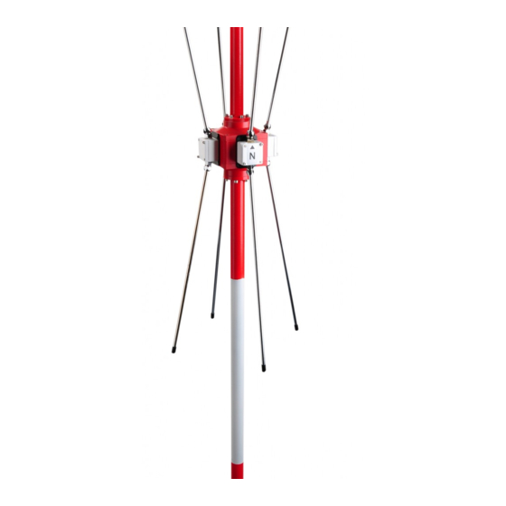
RT-1000 Antenna 1 General Description The antenna mast is a girder mast which has been developed especially for the Doppler antenna system RTA 1300, which makes possible the turning and titling of the antenna for assembly and maintenance purposes. The mast will be delivered in disassembled condition. It has to be mounted and grounded after the assembly on a suitable base. -
Page 5: Part List
RT-1000 Antenna 2 Part List Part List Pos. Component Number Support Tube Base Plate (bottom) Support Tube Clamp (pre-assembled) Cover Plate (above) 10° Step Angle Disk with Tilting Joint Vertical Brace (l = 600) Vertical Brace with Fixed Clamp (l = 600) -
Page 6: Assembly Of The Mast
RT-1000 Antenna 3 Assembly of the Mast After unpacking and comparing the supplied parts to the list of parts, the assembly can be done. If you want to assemble the mast in a closed room, you should make sure that doors and windows are large enough to transport the assembled mast out of the room. -
Page 7: Installation
RT-1000 Antenna 4 Installation Installation Procedure Step Description Figure Set the four support tubes according to Figure 1 on the ground. The two supporting tubes with the fixing clamps for the installations box have to be set mirror reversed to each other on the floor. The two other support tubes have to be set in the same way, also the mirror reversed. - Page 8 RT-1000 Antenna Installation Procedure Step Description The second couple of support tubes has to be treated similarly; however, you don't have to mount a cross brace to permit a tilting of the mast tube for mounting the antenna. Figure 3 Now you have to install the remaining vertical and cross braces on one of the support tube pairs.
- Page 9 RT-1000 Antenna Installation Procedure Step Description Figure You next put the second support tube pair congruent on the pair with the already assembled brace with the "internal side" towards each other (Figure 3). The two support tube pairs are now connected.
- Page 10 RT-1000 Antenna Installation Procedure Step Description Now the mast can be installed on the flat ground. All screws have to be tightened. The eight suspension braces for the mast foot plate needs to be installed now on the fish plates, which have remained free (Figure 7).
- Page 11 RT-1000 Antenna Installation Procedure Step Description Now you have to fix the sun shades with the supplied screws M8 X 40. First the screws are bolted from the inside to outside. You'll use 2 washers per screw and seal them with silicone before tightening.
-
Page 12: Functional Descriptions
RT-1000 Antenna 5 Functional Descriptions An appropriate location of the antenna is prerequisite for the proper function of the direction finder, which precludes possible disturbing reflections by surrounding buildings, forest or geographic circumstances. 5.1 Tilting of the Mast To avoid damage to the sensitive antenna beams, you can turn the mast tube for assembly and maintenance through 90°. -
Page 13: Base
RT-1000 Antenna 6 Base The base for antenna mast RTA-l306 C consists of 4 single concrete bases. The floor plates of the antenna mast will be fixed on these concrete bases by screwed anchors. The bases can be produced by using concrete pipe tubes (DIN 4032 or similar) of at least 30 cm inner diameter and 1 m length as permanent shuttering. - Page 14 RT-1000 Antenna RHOTHETA Page 14 of 17 User Manual...
- Page 15 RT-1000 Antenna RHOTHETA Page 15 of 17 User Manual...
-
Page 16: Lightning Rod / Grounding
RT-1000 Antenna 7 Lightning Rod / Grounding For grounding, dig a hot zinc dipped strip iron (30 x 3.5 mm) of 10 – 15 m length approx. 1 m deep into the ground. Pay attention that the strip iron will not be affected by field work or ground moving especially in agricultural areas. -
Page 17: Notes
RT-1000 Antenna 9 Notes RHOTHETA Page 17 of 17 User Manual...
Need help?
Do you have a question about the RT-1000 and is the answer not in the manual?
Questions and answers