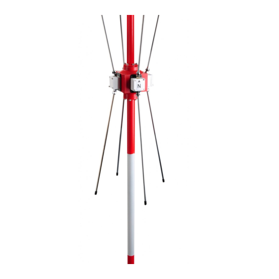
Rhotheta RT-1000 User Manual
Antenna control
Hide thumbs
Also See for RT-1000:
- User manual (30 pages) ,
- Maintenance manual (20 pages) ,
- Installation manual (18 pages)
Table of Contents
Advertisement
Quick Links
Advertisement
Table of Contents

Subscribe to Our Youtube Channel
Summary of Contents for Rhotheta RT-1000
- Page 1 User Manual RT-1000 Antenna Control...
- Page 2 Tel.: +49 8841 4879 - 0 Fax: +49 8841 4879 - 15 Internet: www.rhotheta.de E-Mail: email@rhotheta.de Copyright © RHOTHETA Elektronik GmbH All rights reserved Issue: 2016/01/28 [Rev 1.00] Document-ID: 12-9-3-1-00023-3-3-60 Note The manufacturer reserves the right to make modifications at any time and without previous information of the here described product.
-
Page 3: Table Of Contents
RT-1000 Antenna Control Content Description ........................4 Front View ........................4 Rear View.......................... 5 R/L OFF Button ........................ 6 Interfaces .......................... 6 Antenna Control Jack ..........................6 Backplane Interfaces ..........................7 Signal Sequences ........................... 8 5.3.1 Antenna Control Signal ......................8 5.3.2... -
Page 4: Description
Hence, the Doppler modulation is generated. The RT-1000 Direction Finder system operates on the Doppler principle. To compensate the bearing deviation due to the group delays of the filter components, the antenna rotation is performed 32 times clockwise and 32 times counter clockwise. -
Page 5: Rear View
RT-1000 Antenna Control 3 Rear View RHOTHETA Page 5 of 10 User Manual... -
Page 6: L Off Button
RT-1000 Antenna Control 4 R/L Off Button The R/L Off button interrupts the right/left antenna rotation. If this button is pressed and the received signal is present, the value of 000° or 180°+ north adjustment (set in the system) appears on the QDM display of the controller. -
Page 7: Backplane Interfaces
RT-1000 Antenna Control 5.2 Backplane Interfaces Backplane Interfaces Connector Pin Signal Function Internal connection -15 V DC Supply Input -15 V +15 V DC Supply Input +15 V +5 V DC Supply Input +5 V DC Supply Input Ground WEST... -
Page 8: Signal Sequences
RT-1000 Antenna Control 5.3 Signal Sequences 5.3.1 Antenna Control Signal Set the trigger top channel 1 Channel 1 – West Channel 2 - East Channel 3 – South Channel 4 - North Limits: ≥ + 8,5 V high 5.3.2 6,144 MHz Reference Signal Limits: ≥... -
Page 9: R/L Pulse
RT-1000 Antenna Control 5.3.3 R/L Pulse Limits: = 5,1 µs ± 0,2 µs high = 21,3 ms ±0,5 ms ≥ + 1,0 V high ≤ + 0,2 V RHOTHETA Page 9 of 10 User Manual... -
Page 10: Notes
RT-1000 Antenna Control 6 Notes RHOTHETA Page 10 of 10 User Manual...


Need help?
Do you have a question about the RT-1000 and is the answer not in the manual?
Questions and answers