Rhotheta RT-1000 User Manual
Antenna vhf bearing-system
Hide thumbs
Also See for RT-1000:
- User manual (30 pages) ,
- Maintenance manual (20 pages) ,
- Installation manual (18 pages)
Table of Contents
Advertisement
Quick Links
Advertisement
Table of Contents

Related Manuals for Rhotheta RT-1000


Summary of Contents for Rhotheta RT-1000
- Page 1 User Manual RT-1000 Antenna VHF Bearing-System...
- Page 2 Tel.: +49 8841 4879 - 0 Fax: +49 8841 4879 - 15 Internet: www.rhotheta.de E-Mail: email@rhotheta.de Copyright © RHOTHETA Elektronik GmbH All rights reserved Issue: 2016/11/04 [Rev 1.01.a] Document-ID: 12-9-2-0019-3-1-60 Note The manufacturer reserves the right to make modifications at any time and without previous information of the here described product.
-
Page 3: Table Of Contents
RT-1000 Antenna Content General Information ......................4 Reflections and their Influence to the Bearing Result................5 Influence of the signal ground reflection to the DF accuracy ..............9 Antenna Construction ....................14 Side View .............................. 14 Bottom View ............................15 Component List ............................. -
Page 4: General Information
The achievable bearing accuracy depends largely on the physical conditions at the antenna location. The remote concept of the RT-1000 C DF-System separates the antenna and the high frequency components (RF-Antenna, Receiver Unit) from the controller side (Controller) with the signal processing. So it is easy to place the antenna somewhere in the open field where the physical conditions are good, while the Controller is located at the tower side. -
Page 5: Reflections And Their Influence To The Bearing Result
RT-1000 Antenna 1.1 Reflections and their Influence to the Bearing Result. The antenna of a DF-System can be seen as a sensor, which analyses the incoming electromagnetic wave field to find out where it comes from. As the waves on quiet water surface also radio waves in the free (unobstructed) field dispread circular from around the transmitter. - Page 6 RT-1000 Antenna the plane path to the receiver. Part b) is the vertical projection of part a). The circles represent the lines of equal phase relations for even waves. If the distance between transmitter and receiver is adequate, these are practically straight lines when they reach the receiver location.
- Page 7 RT-1000 Antenna Conditions at airports are much more favourable. These instructions are intended to allow the best positioning of the direction finder antenna. Of course, airports are not without reflectors, but these do not normally cause noticeable problems. All direction finders with field probes calculate the angle of signal incidence by finding out the path direction (vector), at which the largest phase modification per unit of distance is present.
- Page 8 RT-1000 Antenna Aeroplane Aeroplane Reflector Direction finder Reflector Direction finder Fig. 3: Reflected path distance an direct path distance of the radio wave favourable: unfavourable: W1/W2 » R1/R2 W1/W2 ≈ R1/R2 With moving transmitter: Rapid phase shifting between W and Only very slow phase shifting between W and R signal, therefore good bearing average.
-
Page 9: Influence Of The Signal Ground Reflection To The Df Accuracy
RT-1000 Antenna 1.2 Influence of the signal ground reflection to the DF accuracy The signal out of an aircraft transmitter will reach the DF antenna on the direct way. In addition a part of the signal will be reflected on the ground and will reach the antenna as well. - Page 10 RT-1000 Antenna Vertical diagram for h = 23 m Vertical diagram for h = 3.5 m Fig. 5: Signal strength lobes plotted against angle of elevation The zeros of the vertical diagram can be determined using the following formula: λ...
- Page 11 The cause is that alternately, the field strength of the direct, or of the reflected signal, will predominate (see Fig. 6). If the antenna is mounted on the RHOTHETA antenna mast RT-1306, the antenna head is about 4 Meters above the ground. The 1 zero point will be in an elevation of approx.
- Page 12 RT-1000 Antenna N u l l s t e l l e M a x i m u m N u l l s t e l l e M a x i m u m N u l l s t e l l e...
- Page 13 GPS of the aircraft or vessel. While the test flight the pilot gives the GPS bearing to the DF side. Here it both bearings can be compared. RHOTHETA can support you in this matter with an automatic test recording system.
-
Page 14: Antenna Construction
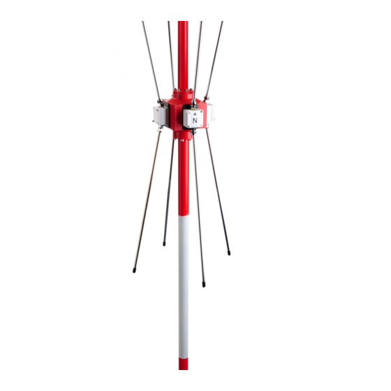
RT-1000 Antenna 2 Antenna Construction 2.1 Side View Fig. 8: RTA 1300.A Direction Finder Antenna RHOTHETA Page 14 of 30 User Manual... -
Page 15: Bottom View
RT-1000 Antenna 2.2 Bottom View X 17 Fig. 9: RTA 1300.A Direction Finder Antenna (Bottom View) RHOTHETA Page 15 of 30 User Manual... -
Page 16: Component List
RT-1000 Antenna 2.3 Component List Installation of the Antenna Pos. Connector Function Lightning conductor rod Radiator cover Radiator Clamping nut Radiator flange Antenna head North dipole label Mast tube X 21 Flat plug for control cable connection X 13 Flat plug for control cable connection... -
Page 17: Assembly Instructions
RT-1000 Antenna 3 Assembly Instructions Installation of the Antenna Step Description Fit the O-ring on mast tube O-ring Pull the antenna cable through the mast tube Connect RF cable to the BNC connector Screw cord grid tight to clamp the RF cable Plug the control cables into the connection board •... - Page 18 RT-1000 Antenna Installation of the Antenna Step Description Apply a thin coat of grease to the antenna head/mast tube contact faces. Screw antenna head onto mast tube. Fit O-ring to lightning conductor rod Apply thin coat of grease to antenna head/lightning conductor rod contact faces.
-
Page 19: North Alignment Of The Direction Finder Antenna And Determining The System Accuracy At The Installation Site
LED-based obstacle lights should not be used. LED-based obstacle lights may disturb the reception of the DF system due to the integrated power supply. The use of the RHOTHETA obstacle light as defined in the options list will prevent such problems. - Page 20 RT-1000 Antenna Nevertheless, the setting of the antenna should be carried out as accurately as possible since this makes subsequent measurements easier. Procedure: 1. Mount the direction finder antenna on the antenna mast so that it is free to rotate. Point the marked dipole to the north.
-
Page 21: Flight Checking For Exact North Alignment And Determining The System Accuracy At The Antenna Installation Site
RT-1000 Antenna 5. Rotate the direction finder antenna in the mast mounting until the controller, which is set to the transmitter frequency, indicates the QDM value determined by the compass (set the north adjustment to zero). In this case correcting the antenna setting by rotating... -
Page 22: Determining The Position Using A Theodolite
RT-1000 Antenna 4.2.1 Determining the Position Using a Theodolite • Set up the theodolite in the immediate vicinity of the direction finder antenna, aligned with magnetic north. • The calibration aircraft then flies a circular flight path around the direction finder antenna and transmits a continuous signal. -
Page 23: Evaluation
RT-1000 Antenna 4.3 Evaluation The actual values measured by the direction finder (QDM bearings) are entered in a record for comparison with the desired values (theodolite bearings, GPS bearings, route points from the map). 4.3.1 Evaluation of Direction Finding Signal... - Page 24 RT-1000 Antenna DF Signal 2 R/L Signal Fig. 11: DF Signal 2 and R/L Signal with a modulated reception signal 3. The direction finding signal is very noisy Possible causes: • The field strength of the transmission signal is too low.
-
Page 25: Evaluation Of Qdr Live Display (Green Light Dot Circle)
RT-1000 Antenna 5. Amplitude of R/L blocks is very large • Effect of reflection It is not possible to list all the possible disturbances and influences of direction finding signals here. As a rule it is assumed that if the direction finding signal is undisturbed the bearing shown by the controller is correct. -
Page 26: Evaluation Of Measuring Results
RT-1000 Antenna 4.3.3 Evaluation of Measuring Results The deviations between the desired and actual values are entered in the test record compiled with the aid of the flight check. If in the case of a calibration aircraft the direction finding signal or the green light dot indication is evaluated, the observations made at the corresponding measured values are to be annotated. - Page 27 RT-1000 Antenna Installation of the Antenna Desired Deviation Remarks 260° 259° -1° 270° 270° ±0° 280° 280° ±0° 290° 290° ±0° 300° 302° +2° 310° 311° +1° 320° 319° -1° 330° 330° ±0° 340° 343° +3° 350° 351° -1° In the example, larger deviations occur when measuring for the 20°, 110° and 210° desired values.
-
Page 28: Determining The North Correction
RT-1000 Antenna 4.4 Determining the North Correction To determine the final north adjustment, the average value of the deviation is determined from the test record. To do this, the sum of all the different values (the signs must be taken into account) are added and divided by the number of measurements. -
Page 29: Mechanical Dimensions
RT-1000 Antenna 5 Mechanical Dimensions RTA 1300 Direction Finding Antenna Mast pole with mast pole and lightning conductor rod All dimensions in mm RHOTHETA Page 29 of 30 User Manual... -
Page 30: Notes
RT-1000 Antenna 6 Notes RHOTHETA Page 30 of 30 User Manual...
Need help?
Do you have a question about the RT-1000 and is the answer not in the manual?
Questions and answers