
Subscribe to Our Youtube Channel
Related Manuals for Rhotheta RT-300


Summary of Contents for Rhotheta RT-300
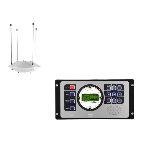
- Page 1 User Manual Installation and Operating 2-Band Precision Bearing System VHF / UHF...
- Page 2 Tel.: +49 8841 4879 - 0 Fax: +49 8841 4879 - 15 E-Mail: email@rhotheta.de Internet: www.rhotheta.de Copyright © RHOTHETA Elektronik GmbH All rights reserved Document Number: 12-9-1-0013-9-2-0001-3-1-60 Issue: 2017/07/27 [Rev 1.04.c] NOTE The manufacturer reserves the right on making modifications at any time and without previous information of the here described product.
-
Page 3: User Manual Bearing System Rt
User Manual Bearing System RT-300 Issue: 2017/06/27 [Rev 1.04.c] Page 3 of 79 12-9-1-0013-9-2-0001-3-1-60... -
Page 4: Table Of Contents
“ERROR“ Message 5.1.10 SCAN-Display 21 5.1.11 Selective Squelch (only ELT) 21 5.1.12 Status Alarm Contact 21 Operating the Bearing System RT-300 5.2.1 Switching On and Off: Key 1: On/Off 21 5.2.1.1 Switching On 5.2.1.2 Switching Off ... - Page 5 User Manual Bearing System RT-300 5.2.4 Squelch Function: Key 14 < Squelch > 23 5.2.4.1 Common Remark 5.2.4.2 Adjusting the Squelch 5.2.5 Volume: Key 5 < Vol.+ > and 10 < Vol.– > 24 5.2.6 „Selective Squelch“: Key 4 < ELT only >...
- Page 6 PRODUCT DISPOSAL Disposal within the European Union Disposal outside the European Union APPENDIX 10.1 Wiring Pattern (recommended RT-300 DCU connections plan) Issue: 2017/06/27 [Rev 1.04.c] Page 6 of 79 12-9-1-0013-9-2-0001-3-1-60...
-
Page 7: Safety Instructions
In addition, it is the responsibility of the user to use the product appropriately. The product RT- 300, a dual-band direction finder system RT-300 may not be used in any way that a person / thing is injured or damaged. -
Page 8: Basic Safety Instructions
2 EU Declaration of Conformity Hereby RHOTHETA Elektronik GmbH declares that the product RT-300 is in compliance with the essential requirements and other relevant provisions of: Directive 1999/5/EC on radio equipment and telecommunications terminal equipment (relevant for RT-300 AU) ... -
Page 9: General Information
The bearing system RT-300 is not approved for primary navigation purposes. 3.1.2 Stationary Use As traffic bearing system the RT-300 has a wide range of use, e.g. surveillance of coastal shipping traffic as well as alerting rescue crews in case of accident. -
Page 10: Front View Dcu (Display Control Unit)
User Manual Bearing System RT-300 3.3 Front View DCU (Display Control Unit) Fig. 1: Front view 3.4 Brief Summary DCU Pos. Designation Function see chapter Switching on and off the bearing system 5.2.1 LED-circle Indicates RB (RB = relative bearing) 5.1.1... - Page 11 User Manual Bearing System RT-300 Pos. Designation Function see chapter Confirms input or selection Call-up menu or leaving menu Live : In bearing-mode: displaying unaveraged 5.2.9 bearing values, if key is pressed. : - In menu-mode: moves selecting field...
-
Page 12: Rear View Dcu
User Manual Bearing System RT-300 3.5 Rear View DCU Fig. 2 Pos. Designation Type plate Antenna connector Ventilation Interface connector Power supply connector Ground (Gnd) Issue: 2017/06/27 [Rev 1.04.c]... -
Page 13: Technical Data
User Manual Bearing System RT-300 4 Technical Data 4.1 Electrical Characteristics Designation Value Remarks Bearing principle Doppler 3 kHz rotational frequency, delay time compensation Direction of bearing - REL - to antenna direction reference, digital display - MAG - relative to magnetic north... - Page 14 User Manual Bearing System RT-300 Designation Value Remarks Current consumption at 12V DC voltage supply: - standby 350 mA (4,8 W) - typ. without ext. speaker 400 mA (5,4 W) - max. without ext. speaker 450 mA (5,4 W) - typ. with ext. speaker 600 mA (7,2 W) - max.
-
Page 15: Mechanical Characteristics
User Manual Bearing System RT-300 4.2 Mechanical Characteristics 4.2.1 DCU 27.8 21.8 58.85 D-Sub connector female D-Sub connector male 30.44 ø4.5 rubber sealing 24.8 26.8 Fig. 3 Weight: ca. 700 g Dimensions: see Fig. 3 Protection of housing: IP 67 Issue: 2017/06/27 [Rev 1.04.c]... -
Page 16: Antenna
User Manual Bearing System RT-300 4.2.2 Antenna Weight: ca. 1300 g Dimensions: see Fig. 4 Protection of housing: IP 67 Antenna beams: 8 pcs. (4 dipoles) The mast flange can be changed by loosening the 6 domed nuts . -
Page 17: Display And Operating
User Manual Bearing System RT-300 5 Display and Operating All display and operating elements are situated on the front of the Display-Control-Unit (DCU). 5.1 Display LED circle general lighting status display display frequency/channel scan display level digital direction of reference... -
Page 18: Lc -Graphic-Display
User Manual Bearing System RT-300 5.1.3 LC -Graphic-Display The centered LC-Display is showing all relevant bearing data, adjustments and status reports. Background brightness may be adjusted in submenu LIGHT/LCD - DIM LCD, contrast in submenu LIGHT/LCD - CONTRAST. When adjusting, the range of adjustment will be displayed as well as the active keys and their function: In menu-mode all selecting fields and adjustments are displayed. -
Page 19: Display Of Signal Level
User Manual Bearing System RT-300 Display Direction of reference Remarks true (geographic) north bearing relative to geographic north optional internal compass module required or compass information via NMEA interface required, input of variation(see 6.2.1.5.4.5.3) 5.1.6 Display of Signal Level The present signal level is displayed as figures (0..99%) as well as... -
Page 20: Error" Message
User Manual Bearing System RT-300 Following warning messages may be displayed: Warning Short Meaning designation U-DISP Voltage supply too low U-REC Antenna voltage too low NO HEAD No heading data available NO COMP No compensation of drag error, selected data source not available or faulty data 5.1.9.2 “ERROR“... -
Page 21: Scan-Display
In order to release this function again, the bearing system has to be switched off and on again (see 6.2.1.5.5.1). 5.2 Operating the Bearing System RT-300 The bearing system can be controlled by using the 13 keys on the front of the DCU. Functions needed for normal bearing operation can be called up directly by function keys. -
Page 22: Switching The Band: Key 16 < Band
User Manual Bearing System RT-300 the last stage before shutting down. If the system was switched on before separating from the operating voltage, it will be switched on after applying the operating voltage. If it was switched off, it will remain switched off. -
Page 23: Squelch Function: Key 14 < Squelch
User Manual Bearing System RT-300 Maritime Band (not available in VHF/UHF-Version): - After pressing key 15 < Channel / Freq. > the „Set Channel“- window will appear on the display (see Fig. 18). - Keys 5 < + > and 10 < – > are selecting the channel. -
Page 24: Volume: Key 5 < Vol.+ > And 10 < Vol
Unfortunately the distress frequencies are misused for entertainment, from our experience about 4 to 8 times a day. In order to prevent false alarms, the bearing system RT-300 has an integrated function called “selective squelch”. If activated, all signals not transmitting the specified sweep tone for emergency transmitters will be suppressed. -
Page 25: Activating / Deactivating „Selective Squelch
5.2.7 Scan Function: Key 12 < Scan > 5.2.7.1 Common Remarks The bearing system RT-300 is equipped with only one receiver. If working in the UHF airband, signals in the VHF airband cannot be recognized and vice versa. So, a certain risk exists not to receive a distress signal and not activating the alarm. -
Page 26: Activating Scanning Function
User Manual Bearing System RT-300 5.2.7.2 Activating Scanning Function Pressing key 12 < Scan >, the scanning window in the display is opened as shown in Fig. 23. Confirming within 5 sec with key 6 < Ok > activates the scanning function. The display „SCAN“ will appear in the LC- display. -
Page 27: Function Live: Key 8 < Live
User Manual Bearing System RT-300 5.2.9 Function Live: Key 8 < Live > The bearing system is processing 750 single bearing procedures per second. These single bearings may be varying in a significant range, depending on signal strength and modulation. -
Page 28: The Menu
User Manual Bearing System RT-300 6 The Menu Adjustments and also system configurations, which have not to be changed during bearing operations, are to be selected and adjusted in the menu. Further information’s as serial numbers or software versions are available. -
Page 29: The Menu Structure
User Manual Bearing System RT-300 6.1 The Menu Structure 1. Level 2. Level 3. Level 4. Level DIM LCD DIM LEGEND Light DIM CIRCLE LCD CONTRAST Bearing Type Bearing View Bearing Setup Beacon Receiver Info Statistics Beep Volume Sounds Alarm Volume... -
Page 30: The Main Menu
User Manual Bearing System RT-300 6.2 The Main Menu 6.2.1 Structure Fig. 27 CANCEL Issue: 2017/06/27 [Rev 1.04.c] Page 30 of 79 12-9-1-0013-9-2-0001-3-1-60... -
Page 31: Menu Light/Lcd
User Manual Bearing System RT-300 Pressing key 7 < Menu > in the bearing mode will call up the main menu. Following submenus may be selected: a) LIGHT/LCD: Adjustments of the LC-display´s lighting, keyboard, LED-circle and the display´s contrast b) BEARING:... -
Page 32: Adjusting Brightness Of Keyboard Lighting: Function Dim Legend
User Manual Bearing System RT-300 6.2.1.1.2 Adjusting Brightness of Keyboard Lighting: Function DIM LEGEND Menu LIGHT/LCD DIM LEGEND In the submenu LIGHT/LCD select function DIM LEGEND. The bar graph as shown in Fig. 30 will appear. Fig. 30 - Adjust brightness of the keyboard lighting using keys 5 <... -
Page 33: Menu: Bearing
User Manual Bearing System RT-300 In case of wrong display contrast please proceed as follows: Switch off device using key 1 < On/Off >. Keep pressed key 7 < Menu > and Switch on device using key 1 < On/Off >. - Page 34 User Manual Bearing System RT-300 NOTE For the determination of the relative bearing no compass information (via NMEA interface or compass module) is required (see. 5.2.8). So, the relative bearing value is available if an external compass is out of order.
- Page 35 User Manual Bearing System RT-300 6.2.1.2.1.3 Reference Direction: Geographic North (True North) - TRUE If compass data, basing on true (geographic) north, are available at the interface, bearing values referring to true north can be put out. Choose in submenu BEARING -TYPE selection TRUE (= true north).
-
Page 36: Display Bearing Parameters: View Bearing Setup
User Manual Bearing System RT-300 6.2.1.2.2 Display Bearing Parameters: VIEW BEARING SETUP Menu BEARING VIEW BEARING SETUP In the submenu BEARING select display function VIEW BEARING SETUP, see Fig. 40. Fig. 40 The important bearing adjustments are shown here. Designation... -
Page 37: Info Receiver
User Manual Bearing System RT-300 6.2.1.3.2 INFO Receiver Menu INFO RECEIVER In the submenu INFO select display function RECEIVER. The display Fig. 43 appears as shown in Fig. 43. Here the important data of the receiver can be seen: Designation... -
Page 38: Menu Sounds
User Manual Bearing System RT-300 6.2.1.4 Menu: SOUNDS Menu SOUNDS In submenu SOUNDS, the volume of keyboard signals and of Fig. 46 the alarm sound may be adjusted. 6.2.1.4.1 Adjusting Key Volume: Function BEEP VOLUME Menu SOUNDS BEEP VOLUME In this menu the volume of the short audible tone, if pressing a key, can be adjusted. -
Page 39: Menu Setup
User Manual Bearing System RT-300 6.2.1.5 Menu: SETUP Menu SETUP Fig. 49 In submenu SETUP all operating setups can be done. Prior putting into operation the bearing system, all setups have to be checked, and if required adapted. ATTENTION Faulty setups may lead to considerable misfunctions, which may not be recognized immediately. - Page 40 User Manual Bearing System RT-300 ATTENTION Setup adjustments in this menu are influencing the bearing result. Faulty setups may lead to wrong bearing results, and it may not be possible, to recognize this error immediately. In case of doubt don´t hesitate to contact the service or the service hotline of RHOTHETA.
- Page 41 User Manual Bearing System RT-300 With a low averaging level the display becomes a kind of nervous, especially with modulated, weak signals. The factory default has the averaging level 5 and is a good compromise. Operating: In submenu BEARING select function AVERAGING.
- Page 42 User Manual Bearing System RT-300 6.2.1.5.1.3 Selecting Mounting Direction of Antenna: SELECT MOUNTING TYPE Menu SETUP BEARING MOUNTING Fig. 54 Usually the antenna is mounted on top of a mast (see Fig. 55). In special cases it may be necessary to mount the antenna upside down (see Fig.
- Page 43 User Manual Bearing System RT-300 6.2.1.5.1.5 Adj. Extended Display of Last Bearing Result: SET BEARING LAST TIME Menu SETUP BEARING LAST TIME After receiving the last signal, the bearing result is still displayed for a Fig. 58 certain adjustable time. This adjustment is done in submenu BEARING - LAST TIME.
-
Page 44: Setup Menu Receiver
User Manual Bearing System RT-300 6.2.1.5.2 SETUP Menu RECEIVER Menu SETUP RECEIVER In setup menu RECEIVER all adjustments can be done Fig. 60 concerning the bearing receiver and it´s functions. Following adjustments can be done in submenu RECEIVER: Menu short designation... - Page 45 User Manual Bearing System RT-300 6.2.1.5.2.2 Selecting Starting Setup: POWER ON DEFAULT Menu SETUP RECEIVER POWER ON DEFAULT In submenu SETUP - RECEIVER - DEFAULTS it can be selected, if the previous frequency adjustments will be overtook or if channel 16 Fig.
-
Page 46: Setup Menu: Serial
User Manual Bearing System RT-300 - The active selection is shown inverted. - Key 6 < Ok > will confirm selection. - Key 9 < Clr > will reject the selection. The device will return to the next higher level of the menu, working with the previous adjustment. - Page 47 User Manual Bearing System RT-300 See documentation “RT-300 NMEA Serial Communication & Remote Control” describing exactly all these functions. 6.2.1.5.3.2 Adjusting Velocity of Data Transmission: SET SERIAL BAUD RATE Menu SETUP SERIAL BAUD RATE submenu SETUP – SERIAL - BAUD RATE, the velocity of data transmission (Baud Rate) of the serial interface can be adjusted.
- Page 48 Following adjustments are possible: Fig. 68 - NMEA - Binary (at the present no data record defined) NOTE See documentation “RT-300 NMEA Serial Communication & Remote Control” describing exactly all these functions. 6.2.1.5.3.5 Selecting Type of Transmission: SELECT SER. TALK MODE Menu SETUP...
-
Page 49: Setup Menu: Compass
User Manual Bearing System RT-300 - Keys 5 < + > respectively 8 < > and 10 < – > respectively 3 < > are increasing / decreasing the interval. - Key 6 < Ok > will confirm the adjustment. - Page 50 300 NMEA Serial Communication & Remote Control“, describing exactly all these functions). NMEA XXHDM The data source is data of an external compass, connected via a NMEA interface. Data format is XXHDM (see documentation “RT-300 NMEA Serial Communication & Remote Control“, describing exactly all these functions). Operating: - In submenu COMPASS select function TRUE SOURCE.
- Page 51 User Manual Bearing System RT-300 - Keys 5 < > respectively 10 < > and 3 < > respectively 8 < > are selecting the corresponding data source. - The active selection is shown inverted. - Key 6 < Ok > will confirm the adjustment.
- Page 52 User Manual Bearing System RT-300 6.2.1.5.4.3 Input of Static True Value: SET STATIC TRUE HEADING Menu SETUP COMPASS STATIC TRUE In submenu SETUP – COMPASS - STATIC TRUE a constant value (angle) can be related to the direction of reference STATIC Fig.
- Page 53 User Manual Bearing System RT-300 Menu SETUP COMPASS INT. COMPASS CALIBRATION After installing the bearing antenna, the compass should be calibrated. Calibration eliminates environmentally caused interferences of the magnetic field. Calibration improves significantly the precision of the compass. Fig. 77 In order to calibrate the compass, the bearing antenna has to be rotated twice in its vertical axis, the rotational direction doesn´t...
- Page 54 User Manual Bearing System RT-300 6.2.1.5.4.5.2 Input of Compass Error – Deviation: INT. COMPASS DEVIATION Menu SETUP COMPASS INT. COMPASS DEVIATION Deviation is the difference of angle between the actual magnetic north direction and the north direction determined by the internal compass.
-
Page 55: Setup Menu: Other
SETUP OTHER RELAY Menu bearing system RT-300 is equipped with a relay-contact, which is closing if a distress signal is detected. It´s contacts are integrated in the „POWER“ connector (see 6.4.2.3), external devices may be Fig. 83 connected (e.g. GPS MOB-function, alarm bell, warning light, etc.). - Page 56 User Manual Bearing System RT-300 Designation Function Application PULS As soon as a signal is For the connection of a MOB-function (Man exceeding the squelch Over Board) of a GPS-receiver Storage level, the contact is closing of position at the time of reception. This for a defined time and will function is working on all frequencies.
-
Page 57: Setup Menu: Factory Reset
User Manual Bearing System RT-300 6.2.1.5.5.1.2 Adjusting Pulse Duration of the Relay: MOB PULSE TIME Menu SETUP OTHER RELAY MOB PULSE TIME In submenu SETUP – OTHER – RELAY – MOB PULSE TIME the pulse duration of the relay contact can be adjusted. The adjustment can be made for the relay modes „PULS“... - Page 58 User Manual Bearing System RT-300 Designation Short Designation Factory See chapter default Brightness of LC-display DIM LCD 100 % 6.2.1.1.1 Brightness of keyboard DIM LEGEND 50 % 6.2.1.1.2 Brightness LED-circle DIM CIRCLE 100 % 6.2.1.1.33 Contrast of LC-display LCD CONTRAST 45 % 6.2.1.1.44...
-
Page 59: Menu: Service
User Manual Bearing System RT-300 6.2.1.6 MENU: SERVICE Menu SERVICE Fig. 89 In submenu SERVICE all functions required for the verification of the nominal characteristics of the bearing system, or to support the detection of errors, can be found. 6.2.1.6.1 Service Menu: BEARING... -
Page 60: Service Menu: Receiver
User Manual Bearing System RT-300 6.2.1.6.2 Service Menu: RECEIVER Menu SERVICE RECEIVER Fig. 91 In submenu SERVICE - RECEIVER present receiver parameters are displayed: Designation Meaning STATUS Status of receiver module If no error detected, message OK is displayed. If error detected, the error number is displayed. -
Page 61: Service Menu: Compass
User Manual Bearing System RT-300 6.2.1.6.4 Service Menu: COMPASS Menu SERVICE COMPASS In submenu SERVICE - COMPASS the compass data, available for the different reference directions respectively the internal (optional) compass module, are displayed. Select the reference direction using key 3 < > and 8 < >. -
Page 62: Special Functions
6.3.3 Loading Firmware Updates If there is a new firmware available, it can be uploaded via the interface port on the backside of the DCU. How to proceed is described in the documentation “RT-300 Firmware Update” which is available by contacting RHOTHETA (www.rhotheta.de). -
Page 63: Power Connector
User Manual Bearing System RT-300 Pin wiring: D-Sub-socket Contact Signal Name Signal (PIN) ANT-EAST control signal east ANT-WEST control signal west RS485/A data signal RS485/B data signal 12..28V voltage supply ANT-SOUTH control signal south ANT-NORTH control signal north audio signal... -
Page 64: Power Supply
User Manual Bearing System RT-300 6.4.2.1 Power Supply The power supply is connected to PIN 5: [-] voltage supply GND (ground) and PIN 9: [+] positive voltage supply Permitted range of operating voltage: 11V... 28 V DC Current consumption: max. 800 mA (depending on operating voltage and connected external... -
Page 65: External Speaker
PIN 6 is carrying a test signal, serving for trouble-shooting in the case of service. During operation of the bearing system this contact is not to be connected. 6.4.3 Interface Connector The bearing system RT-300 has different interfaces for data exchange. - RS-232 - RS-422 - RS-485 These interfaces are connected to socket ”Interface Connector“... -
Page 66: Rs-232-Interface
(voltage supply for interface modules) Current output: max. 200 mA Shield Ground 6.4.3.1 RS-232-Interface For interface functions see documentation “RT-300 NMEA Serial Communication & Remote Control” 6.4.3.2 RS-485-Interface For interface functions see documentation “RT-300 NMEA Serial Communication & Remote Control”... -
Page 67: Installation And Putting Into Operation
User Manual Bearing System RT-300 7 Installation and Putting into Operation 7.1 Installation of Display-Control-Unit DCU 7.1.1 DCU Installing Cut-Out The DCU is to be installed in an instrument panel in a suitable position. Therefore, an installing cut-out, as shown in Fig. 98, has to be set. -
Page 68: Connecting Power Supply
User Manual Bearing System RT-300 With a flat screwdriver screw the fixing M4 fastening bolts in the screw jacks of the DCU. Do not tighten the bolts to hard. If, at the attachment site, noticeable vibrations occur (e.g. diesel generator), secure the bolts with LOCTITE-Threadlocker. -
Page 69: Connecting Antenna
User Manual Bearing System RT-300 ATTENTION The antenna´s ground is connected to the DCU. Electrostatic charge may cause very high voltages. Therefore, it is very important earthing the DCU before connecting the antenna. 7.1.4 Connecting Antenna Connect antenna cable (see 7.3) to socket “Antenna Connector“. -
Page 70: Completing Antenna Cable
User Manual Bearing System RT-300 Example Fig. 100: Position : bearing optimal Position : bearing good Position : bearing sufficient Position : bearing sufficient Fig. 100 7.3 Completing Antenna Cable The delivery contains an antenna cable of 10m length. First of all this cable is intended for testing operation of the system. - Page 71 User Manual Bearing System RT-300 Antenna 6 7 8 9 D-Sub-socket D-Sub- connector Kontakt Kontakt Signal-name Signal ANT-EAST control signal east ANT-WEST control signal west RS485/A data signal RS485/B data signal 12...28V voltage supply ...
-
Page 72: Installing The Antenna
User Manual Bearing System RT-300 NOTE With the cable LifYCY6x2x0,50mm (Metrofunk Kabel-Union), an operation with up to 350m cable length is possible. The necessary operating voltage of the device with > 100m cable length is 24V. 7.4 Installing the Antenna The antenna is to be mounted on a suitable mast tube. -
Page 73: Fixing The Antenna
User Manual Bearing System RT-300 7.4.4 Fixing the Antenna - Connect antenna cable and antenna, tighten check-screws. - Put antenna to the mast-flange. Take care, that the o-ring of the antenna flange is fitting firmly into its groove. - Tighten slightly the compression nut (threaded flange). -
Page 74: Mounting Of Antenna Beams
User Manual Bearing System RT-300 Aligning reference direction QUJ (true compass bearing from transmitter to direction finder): To be done as described in "Aligning for reference direction QDM", only the local variation has to be subtracted from the nominal value. -
Page 75: Configuring Setup
User Manual Bearing System RT-300 7.5 Configuring Setup Once antenna and DCU connected to the power supply, the bearing system will work already. The factory defaults are set (see 6.2.1.5.6) in a way, that all standard functions are activated. The bearing system is offering a great number of functions, different settings and external devices may be connected. - Page 76 User Manual Bearing System RT-300 Pos Menu Action Default Remarks chapter. - LAST TIME if factory default is not optimal. Activating heading compensation 6.2.1.5.1.6 Only possible, if external or for repeat function internal compass is available. - LAST VALUE COMPENSATION RECEIVER Selecting frequency mode in 6.2.1.5.2.1 Default setup reasonable, for...
-
Page 77: Maintenance And Cleaning
8 Maintenance and Cleaning 8.1 Maintenance UV irradiation can age the front foil of the RT-300 DCU with time, which can lead to brittleness of the front foil. Depending on the operating conditions of the RT-300 DCU, there is the possibility that moisture can penetrate through small hairline cracks in the front foil. -
Page 78: Product Disposal
Therefore, supply the device to an electronics recycling after the final taken out of service. The RHOTHETA Elektronik GmbH takes back all products that are subject to the requirements of the WEEE Directive (2002/96/EC) of the European Union to supply these products to professional disposal. -
Page 79: Appendix
User Manual Bearing System RT-300 10 Appendix 10.1 Wiring Pattern (recommended RT-300 DCU connections plan) Issue: 2017/06/27 [Rev 1.04.c] Page 79 of 79 12-9-1-0013-9-2-0001-3-1-60...
Need help?
Do you have a question about the RT-300 and is the answer not in the manual?
Questions and answers