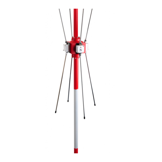
Rhotheta RT-1000 Maintenance Manual
Multichannel
Hide thumbs
Also See for RT-1000:
- User manual (30 pages) ,
- Installation manual (18 pages) ,
- User manual (27 pages)
Table of Contents
Advertisement
Quick Links
Advertisement
Table of Contents

Summary of Contents for Rhotheta RT-1000
- Page 1 RT-1000 Multichannel Maintenance Manual...
- Page 2 RT-1000 MC Maintenance Manual Edited by: RHOTHETA Elektronik GmbH Kemmelpark Dr.-Ingeborg-Haeckel-Str. 2 82418 Murnau Germany Tel.: +49 8841 4879 - 0 Fax: +49 8841 4879 - 15 Internet: www.rhotheta.de E-Mail: email@rhotheta.de Copyright © RHOTHETA Elektronik GmbH All rights reserved Issue: 2016/11/07 [Rev 1.03.a]...
-
Page 3: Table Of Contents
RT-1000 MC Maintenance Manual Content General Information ......................4 Indoor Tests ........................5 AC Power Supply ............................ 5 DC Power Supply ........................... 6 RF-Splitter ............................... 8 DF-Channels ............................9 2.4.1 Display and Control Elements ....................9 2.4.2 Phase Adjust ..........................10 2.4.3... -
Page 4: General Information
All tests described in this document are recommended to be performed annually in order to proof the correct functionality of the DF-System. All tests should be performed by the personnel, which have been educated on the RT-1000 DF-System or have other appropriate knowledge. -
Page 5: Indoor Tests
RT-1000 MC Maintenance Manual 2 Indoor Tests 2.1 AC Power Supply Test procedure: Measure the input supply voltage in the supply socket with a RMS Voltmeter. TC.Nr. TC. Name Test point Limits Result Passed Supply [TC 010.10] AC Supply Input (UPS) 230V ±15%... -
Page 6: Dc Power Supply
RT-1000 MC Maintenance Manual 2.2 DC Power Supply Test procedure: Switch on the DC Power Supply (KEPCO-POWER-SUPPLY +5 V, +15V, -15V). Measure the DC Voltage on DC Power Supply’s front panel test points with a RMS Voltmeter. TC.Nr. TC. Name... - Page 7 RT-1000 MC Maintenance Manual Test procedure: Measure the DC Voltage with a RMS Voltmeter on one of the DF-Channels from TP16 to GND, TP15 to GND, TP14 to GND TC.Nr. TC. Name Test Limits Result Passed point [TC 020.20] +5 V TP16 +5,0…+5,25 V...
-
Page 8: Rf-Splitter
RT-1000 MC Maintenance Manual 2.3 RF-Splitter Test procedure: Disconnect the DF-Antenna from RF-IN on connector panel (see: General System Description, Chapter: Connector Panel). Connect 50Ω load to RF-IN on connector panel. Measure the attenuation of RF-Splitter: Connect the RF-Generator (Level 0 dBm) to the input TEST-IN of RF-Splitter and measure the output levels at LNA1-OUT and LNA2-OUT. -
Page 9: Df-Channels
RT-1000 MC Maintenance Manual 2.4 DF-Channels 2.4.1 Display and Control Elements Test procedure: Connect the RF-Generator to the antenna model Input. Connect the antenna model output to the Test In port of the RF-Splitter. Switch on the RF-Generator. f = 127.000 MHz, Level = 0 dBm, Modulation AM: 800 Hz, m=60%. -
Page 10: Phase Adjust
RT-1000 MC Maintenance Manual 2.4.2 Phase Adjust Test procedure: Connect the antenna model to the RF-IN of the RF-Splitter. Connect the RF-Generator with 127.000 MHz and with a level of -7 dBm at the antenna model RF input. Adjust the receiver to the 127.000 MHz. Switch the Antennal Model to 000°... -
Page 11: Frequency Offset Test
RT-1000 MC Maintenance Manual 2.4.3 Frequency Offset Test 25 kHz Channel Spacing Test procedure: Connect signal generator to RF-Splitter TEST-IN. Change Frequency ±10 kHz Control LED «F+, F-» on one of the DF-Channels. Frequency: 127,000 MHz Level: -60 dBm Modulation: TC.Nr. - Page 12 RT-1000 MC Maintenance Manual 8.33 kHz Channel Spacing Test procedure: Connect signal generator to RF-Splitter TEST-IN. Change Frequency ±4 kHz Control LED «∆f+», «∆f-» on one of the DF-Channels. Frequency: 127,005 MHz Level: -60 dBm Modulation: TC.Nr. TC. Name Criteria...
-
Page 13: Level Check
RT-1000 MC Maintenance Manual 2.4.4 Level Check Test procedure: Connect the RF-Generator to the TEST-IN of the RF-Splitter. Set RF-Generator output to appropriate level (see column Criteria). Check dBm level displayed on DF Commander. Also check % level displayed on DF Commander. -
Page 14: Squelch Check
RT-1000 MC Maintenance Manual 2.4.5 Squelch Check Test procedure: Set Squelch Level (SQ) of DF-Channels to 50%. Connect the RF-Generator to the TEST-IN of the RF-Splitter. Set RF-Generator output level to -80 dBm at the desired cannel frequency of DF-Channel. -
Page 15: Bearing Check
RT-1000 MC Maintenance Manual 2.4.6 Bearing Check Test procedure: Connect the RF-Generator to the input of antenna model. Connect the output of the antenna model to the TEST-IN port of the RF-Splitter and switch ON the RF-Generator. f = 127,000 MHz, Level = -10 dBm Modulation off. Control the displayed bearing at the DF Commander at Main Bearing Page for each channel. -
Page 16: System Status Check
RT-1000 MC Maintenance Manual 2.5 System Status Check 2.5.1 Status Test procedure: Check the appearance of Errors and Warnings on the Channel Status Indicator (see Manual). There should be no Errors and Warnings displayed (all indicator must be green). TC.Nr. -
Page 17: Ups Duration Test
RT-1000 MC Maintenance Manual 2.6 UPS Duration Test Test procedure: Turn off input supply from UPS. The System has to work 30 minutes without Errors. After test turn UPS input supply ON. TC.Nr. TC. Name Passed Supplied [TC 060.10] 30 minutes operation from UPS... -
Page 18: Bearing Test With Antenna Mast
RT-1000 MC Maintenance Manual 3.1 Bearing Test with Antenna Mast Test procedure: 1. Please define the position on the field, where the bearing is known. The distance should be at least 100m. 2. Go to the defined position and switch on the radio transmitter on the appropriate test frequency. -
Page 19: Bearing Test Without Mast
RT-1000 MC Maintenance Manual 3.2 Bearing Test without Mast Test procedure: 1. Please define more than one position, where the bearing is known. 2. Go to the defined position and switch on the radio transmitter on the appropriate test frequency. -
Page 20: Notes
RT-1000 MC Maintenance Manual 4 Notes RHOTHETA Page 20 of 20 Maintenance Manual...


Need help?
Do you have a question about the RT-1000 and is the answer not in the manual?
Questions and answers