Table of Contents
Advertisement
Advertisement
Table of Contents

Related Manuals for Cardioline cubestresslite


Summary of Contents for Cardioline cubestresslite
- Page 1 User manual Rev. 10 – 05/07/2019 1936...
- Page 2 All rights reserved © Cardioline SpA. CARDIOLINE® is a registered trademark of Cardioline SpA. This publication may not be reproduced, in whole or in part, in any form or manner, without prior written authorisation Cardioline Spa Via Linz, 151...
-
Page 3: Table Of Contents
Contents GENERAL INFORMATION .........................1 1.1. Minimum Requirements for the computer ..................1 1.2. Licensing terms ..........................1 1.3. Other important information ......................2 SAFETY INFORMATION ..........................3 SYMBOLS AND LABEL ..........................7 3.1. Explanation of the symbols ......................7 3.2. Device label ............................7 INTRODUCTION ............................9 4.1. - Page 4 6.4.1. Enter a pressure measurement ....................34 6.4.2. End the examination ........................34 6.5. Defining a protocol ..........................35 6.5.1. Create a new protocol ......................35 6.5.2. Modifying a protocol ........................37 6.5.3. Default protocols ........................37 6.6. Signal display windows ........................38 6.6.1. Real Time ECG window ......................38 6.7.
-
Page 5: General Information
Have the operator read the manual thoroughly, as a great deal of the information is only described once. This manual is to be regarded as part of the cubesuite manual, of which cubestresslite is one of the specific features. Have the operator read the cubesuite manual thoroughly, as a great deal of the information is only described once. -
Page 6: Other Important Information
Other important information This manual was written with the utmost care. Should you find any details which do not correspond to those contained in this manual, please inform Cardioline SpA, who will proceed to correct such inconsistencies as soon as possible. -
Page 7: Safety Information
SAFETY INFORMATION SAFETY INFORMATION Cardioline SpA will be held responsible for the safety, reliability and functionality of the devices only if: 1. Assembly, modification or repair operations are carried out by Cardioline SpA or by one of its Authorised Assistance Centres;... - Page 8 SAFETY INFORMATION If the support device is battery powered, do not connect it to an external power supply (for recharging) or other electrical equipment (e.g. to another computer via USB or to a LAN network) when using it in the patient area.
- Page 9 SAFETY INFORMATION Do not leave the electrodes unattended in the presence of children as they could cause suffocation if accidentally swallowed. Attention The device does not require any calibration or special instrumentation for correct use and maintenance.
- Page 10 SAFETY INFORMATION...
-
Page 11: Symbols And Label
SYMBOLS AND LABEL SYMBOLS AND LABEL 3.1. Explanation of the symbols Refer to the cubesuite manual for a complete description of the symbols. 3.2. Device label Refer to the cubesuite manual. - Page 12 SYMBOLS AND LABEL...
-
Page 13: Introduction
(stress tests). In any case, a Cardiologist must validate the data presented. cubestresslite is intended for use in hospitals, clinics and outpatient departments of any size. The device acquires, analyses, displays and prints out electrocardiograms and electrocardiographic examinations under stress. -
Page 14: Description Of The Device
4.5. General overview Cubestresslite shares the overall UI with the cubesuite software, from which you access to the main specific window of the cubestresslite program. Refer then to the cubesuite manual for a general description of the overall interface and its key features. -
Page 15: Control Panel
INTRODUCTION Cubestresslite main window A. Application bar B. Main menu C. Control Panel D. Toolbar E. Status Bar F. Display Windows 4.5.1. Control Panel It’s a vertical area on the right side of the Main Window, which contains the information and the control keys... - Page 16 INTRODUCTION Control Panel A. Heart Rate (HR): value of HR in beats per minute (bpm). B. Percentage Value: percentage ratio between current Heart Rate (HR) and Theroetical Maximum Heart Rate (HRMax). C. Pressure: Systolic and Diastolic Pressure in mmHg. Pressing the button shows a window allowing you to manually enter the measurement.
-
Page 17: Toolbar
INTRODUCTION 4.5.2. Toolbar It is located under the main Menu and allows quick access, using graphical buttons (icons), to the most common operations. Toolbar Print Button This button give immediate access to the Print Page operations. Buttons for changing the Display Mode These buttons allow immediate access to the Display Mode. -
Page 18: Status Bar
INTRODUCTION 4.5.3. Status Bar It is a horizontal bar on the bottom of the Main Window, and displays various information about the status of the test in progress. Some information can be edited with a click of the mouse: a window that allows seeing more details appears. - Page 19 INTRODUCTION Opens the Real Time ECG Mode Real Time ECG page Opens the Trend Mode Trend page ECG menu SHIFT+ Sensitivity - Decreases the ECG sensitivity. DOWN SHIFT+ Sensitivity + Increases the ECG sensitivity. CTRL+ Speed - Decreases the ECG speed.
-
Page 20: Display Windows
INTRODUCTION Gives information about the program version. 4.5.5. Display windows The Windows are rectangular portions of the screen that allow accessing various display modes of the ECG tracing and of the analysis results. The available Windows are listed in the Table. -
Page 21: Preparation For Use
PREPARATION FOR USE PREPARATION FOR USE 5.1. Installing the software Refer to the cubesuite manual for software installation instructions. 5.2. Connecting and configuring the HD+ acquisition unit To acquire the electrocardiographic signal, the HD+ acquisition device must be connected to the computer running the software (configured appropriately). - Page 22 PREPARATION FOR USE 2. Insert the support for the central tube into the base and insert the tube into the support. Align the holes and fully tighten the screws.
- Page 23 PREPARATION FOR USE 3. Insert the following into the central tube in this order: the printer shelf, the main shelf, the basket and the support for the all-in-one computer. The Digital model trolley is suitable for use with an all-in-one computer.
- Page 24 PREPARATION FOR USE Fastening plate and fastening the computer with the screws 2. Place the thermal battery-powered printer (if available) on the opposite shelf and connect it to the all-in-one computer using the USB cable provided. 3. If the HandyVAQ ECG suction cable is available, fix the cable-holder support to the trolley and fasten the HandyVAQ to the cable-holder support.
- Page 25 PREPARATION FOR USE 4. Connect the HandyVAQ (if available) to the HD+ acquisition device and to the PC: connect connector (A) to the patient cable connector of the HD+ (A) and the USB connector (B) to a USB port on the PC (see figure).
- Page 26 In the Windows control panel Devices And Printers > Device Manager > COM and LPT ports check the serial port number assigned to the adapter, required to configure the cubestresslite software. When the system has been mounted it should appear as follows:...
-
Page 27: Installation Of The Systems With Full Model Trolley
PREPARATION FOR USE 5.3.2. Installation of the systems with Full model trolley The full model trolley is already mounted, but you need to assemble the computer and the other components: 2. Fasten the monitor support: a. Remove the drawer b. - Page 28 PREPARATION FOR USE b. Top shelf: monitor cable, monitor power supply cable, audio cable, USB extension for bluetooth dongle (if present). Back Monitor support 5. Install the isolation transformer, if available: a. Insert the power supply plug into the transformer and fasten the cable with the ‘power cord restraint Kit’.
- Page 29 PREPARATION FOR USE 6. Installing the printer: a. Plug the power supply and USB cables into the printer. b. Slide the cables through the rear panel of the trolley and place the printer on the special compartment on the shelf, as shown in figure.
- Page 30 PREPARATION FOR USE 8. If the HandyVAQ ECG suction cable is available, fix the cable-holder support to the trolley using the holes located on the back of the trolley (A), and fasten the HandyVAQ to the cable-holder. 9. Connect the HandyVAQ (if available) to the HD+ acquisition device and to the PC: connect connector (A) to the patient cable connector of the HD+ (B) and the USB connector (C) to a USB port on the PC (see figure).
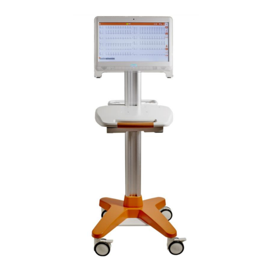
- Page 31 PREPARATION FOR USE 11. Activate the trolley by switching on the green button on the back of the trolley. When the system has been mounted it should appear as in the figure below: System assembled...
- Page 32 PREPARATION FOR USE...
-
Page 33: Execution Of The Examination
EXECUTION OF THE EXAMINATION EXECUTION OF THE EXAMINATION 6.1. General procedure To execute an examination proceed as follows: 1. Prepare and connect the patient (par. 6.2). 2. Start the program (par. 6.3). 3. Define a test protocol (par. 6.4). -
Page 34: Connecting The Patient
EXECUTION OF THE EXAMINATION NOTE: Pay attention not to cause abrasions, discomfort or bruises on the skin. Always observe the utmost clinical discretion when preparing the patient. 6.2.2. Connecting the patient It is important to position the electrodes properly in order to acquire a good electrocardiographic signal. -
Page 35: Program Start-Up
Program start-up You need to start the cube software from the Windows Start Menu to start the test. Start > Programs > Cardioline > Cube When the Login Window appears, enter User Name and Password. You can use the default values:... -
Page 36: Start And Execution Of The Examination
EXECUTION OF THE EXAMINATION 6.4. Start and execution of the examination After choosing “New examination” and selecting Stress-test from the drop down menu as explained in the previous paragraph, a wizard starts, allowing beginning the examination. Specifically you need to: 1. - Page 37 EXECUTION OF THE EXAMINATION 6. Select the protocol: select the operating Protocol from the list, choosing the type of ergometer and protocol. 7. Now the examination is in the “Pre-exercise” warm-up phase of the patient. By pressing the “Start...
-
Page 38: Enter A Pressure Measurement
EXECUTION OF THE EXAMINATION 6.4.1. Enter a pressure measurement During the examination you can enter blood pressure measurements by pressing the PA key. If the ergometer is equipped with pressure meter, the PA key starts automatic measuring and receives the reading, otherwise the value can be entered manually. -
Page 39: Defining A Protocol
EXECUTION OF THE EXAMINATION To insert the report you have to press the key with the patient’s name. 6.5. Defining a protocol To set the operating parameters of the ergometers, use the Protocol window accessible from Menu: Menu > Function > Protocols. - Page 40 EXECUTION OF THE EXAMINATION Protocols Window Proceed as follows: 1. Select the protocol type “Cycle Ergometer, Treadmill or Generic” and assign a name 2. Select the load and duration data and follow the wizard.
-
Page 41: Modifying A Protocol
Insert: inserts a new step after the selected one. Edit: allows editing the step parameters. Delete: deletes the selected step 6.5.3. Default protocols The table below shows the cubestresslite default protocols, divided by ergometer type. Ergometer Step Step Load/speed Load... -
Page 42: Signal Display Windows
EXECUTION OF THE EXAMINATION Ergometer Step Step Load/speed Load Slope Protocol Slope incr. type Duration increment range range mod. Naughton Fixed 60" 3.50° 2 Km/h 0-22° Km/h 2.0km/h 2.7-9.6 Bruce Km/h 180" 2° Km/h 22° Mod. Bruce 2.7-8 180"... - Page 43 EXECUTION OF THE EXAMINATION Change Amplitude and Speed The amplitude and speed of th e l e ads can be edited through the Toolbar buttons. Icon Function Description Amplitude Changes the values in 1, 5, 10, 20, 40 mm/mV Changes the values in 1, 5, 10, 12.5, 25, 50, 100, 200...
-
Page 44: Display Modes
EXECUTION OF THE EXAMINATION 6.7. Display modes The display windows are grouped in combinations called Display Mode, each containing at least the Real Time ECG window. You can switch from one mode to another by using the corresponding buttons on the Toolbar. -
Page 45: St Trend Mode
EXECUTION OF THE EXAMINATION ECG - Real Time Mode A. Real Time ECG window B. AVG real time window C. AVG baseline window 6.7.2. ST Trend Mode The ST Trend Mode comprises 3 windows: 1. The Zoom ECG window, in 6/12 channels mode. -
Page 46: Printing The Examination
EXECUTION OF THE EXAMINATION Modifying the look of the Trend windows From Menu>Function>Setup>Trend you can activate the filtering of the data presented on the trend and change the colours of the various graph sections. All the operations described for the Real Time ECG window are also available. - Page 47 EXECUTION OF THE EXAMINATION Icona Tasto Funzione Descrizione AUTO printing 12, 12+AVG, 6+6, 6+6+AVG You can choose print format and the printer to be used from Menu> Function> Setup> Printing. Print setup...
- Page 48 EXECUTION OF THE EXAMINATION...
-
Page 49: Post-Analysis And Report Creation
7.1. General information The program cubestresslite can be used, in addition to managing the stress test in real time, to review the examination, carry out a detailed analysis of the results and print the examination report. This phase is called Post-Analysis. -
Page 50: Displaying The Stress Test
POST-ANALYSIS AND REPORT CREATION The function of the Control Panel becomes displaying all the test data (heart rate, blood pressure, double product, the name of the phase and of the stage, load, etc.), relating to the instant in which the Zoom of the ECG Window is placed. -
Page 51: Printing Reservations
POST-ANALYSIS AND REPORT CREATION 7.3. Printing Reservations From the ECG Zoom and Compacted ECG Window you can select a signal section and open the Drop-down Menu with the right mouse button. The menu features as the last entry print booking: the track selected ECG was then added automatically to your Report. -
Page 52: Printing The Report
POST-ANALYSIS AND REPORT CREATION Reporting Windows 7.5. Printing the Report Icon Function Description REPORT printing Compiling and printing the Report Preview compiling and displaying the Report To print the Report, simply press the Print key in the Toolbar. If you wish to display a Report preview before printing, press the Preview key. - Page 53 POST-ANALYSIS AND REPORT CREATION Report Configuration window A. Cover (examination data and conclusions) and Table (list of the steps performed). B. Table of measurement on ST and/or QT sections. C. Averaging: average heartbeat tracing, with average calculated on 4 seconds or on the whole duration of the step.
- Page 54 POST-ANALYSIS AND REPORT CREATION...
-
Page 55: System Settings
8. SYSTEM SETTINGS SYSTEM SETTINGS 8.1. General information To customise the interface and set the program parameters, use the Setup window: Menu> Function> Setup. The window is organised on multiple tabs: ECG: ECG colors; duration and number of rows of the Compacted ECG window ... - Page 56 Only for cube suite version 1.4.X.1. Only for cube suite version 1.4.X.2. Demo file NOTE: ECG acquisition devices Cardioline clickecg and clickecgBT are no longer sold but can still be used as indicated. They cannot coexist with the Cardioline HD+ device.
-
Page 57: Troubleshooting
9. TROUBLESHOOTING TROUBLESHOOTING The program may display these error messages. Problem Cause Solution Patient First and Last name Compile the Patient First fields are empty and Last name fields. Search BT device… The bluetooth acquisition Verify that the bluetooth device is not detected. - Page 58 9. TROUBLESHOOTING...
-
Page 59: Warranty
WARRANTY Cardioline SpA guarantees this device for a period of 24 months from the date of sale. The date of purchase shall be proven by a document, issued upon delivery, which shall be submitted in the case of any claim under the warranty. - Page 60 Head Office and Production Via Linz, 151 38121 Trento Italy T. +39 0463 850125 F. +39 0463 850088 Sales Office: Via F.lli Bronzetti, 8 20129 Milan, Italy T. +39 02 94750470 F. +39 02 94750471...
Need help?
Do you have a question about the cubestresslite and is the answer not in the manual?
Questions and answers