Table of Contents
Advertisement
Advertisement
Table of Contents

Related Manuals for Rexing M2


Summary of Contents for Rexing M2
- Page 1 Users Manual...
- Page 2 Notice 1. The user menu is to be set up in non-video mode. If the device is in video mode, please proceed only after stopping the video recording. 2. Memory Card: Using a new MicroSD card always requires formatting it to your device.
- Page 3 Warning The battery (module or pack) must not be expose to an overheat environment such as direct sunlight or flame. Never remove, strike, or squeeze the battery or put it in fire. Stop using the battery if it is ballooned, warped, leaking, or shows any other visible signs of damage.
- Page 4 Overview Thank you for choosing REXING! We hope you love your new products as much as we do. If you need assistance, or have any suggestions to improve it, please contact us. You can reach us via care@rexingusa.com or call us at (203) 800 - 4466.
- Page 5 Table of Contents Camera Overview............5 Installation and Operation……………………....8 Basic Operations………………………………………12 Product Specifications……………………………...…32 General Troubleshooting…………………………...…33...
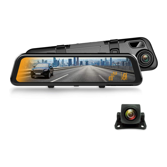
- Page 6 Camera Overview USB Port GPS Port Rearview MicroSD Card Camera Port Slot Display/Touch Screen Front Camera Speaker Reset Key Pinhole Power Key MIC Pinhole...
- Page 7 Designation Description of Functions In connection with an external power source, in the power-off state, press or depress this button to start the device. In a power-on state, depress this button to switch off the device. Power Button In a power-on state, press this button quickly to turn the screen backlight off.
- Page 8 Installation and Operation Due to excessive mishandling, this device could be damaged during transportation. To avoid high cost of troubleshooting and repairs due to repeated mounting and removal, we recommend that you assemble all components first after delivery and test the device with the on-board charger power supply.
- Page 9 Installation Instructions Power Supply Wiring Location Optimum Installation Location of GPS Location Module (Power Supply Wiring Instructions) Install the Rearview Camera (optional) Some rearview cameras are connected through removable coupling connectors. If you receive a product with a separated plug and socketed cable, then connect the plug-in components properly according to the illustrations below.
- Page 10 Align the male portion and the female portion of the rearview camera cable between the arrows before pressing the connectors together. Rearview Camera Wiring Instruction (as shown below) Connected to rearview camera Connected to reversing light The rearview camera has two wire routing options as shown in the above figure.
- Page 11 Note: The device is configured with a streaming media rearview camera that provides clear traffic view behind the car. To obtain clearer and more intuitive images, it is recommended to mount the camera above the license plate (as shown by option B). Instructions for Reverse Trigger Wiring The red wire of the car’s reverse gear wiring is connected to the positive end of one of the car’s reverse light.
- Page 12 Basic Operations I. Video Mode Thursday Key Functions: 1. Return to the main interface 2. Return to the previous operation menu 3. Start/stop video recording 4. Take a snapshot 5. Locking/unlocking (if locked) a file 6. Audio recording on/off 7. Front/rear view switching 8.
- Page 13 11. Video recording state and duration Video Recording Operation: With a MicroSD card inserted in the device, it will record automatically in video mode after starting. A red indicator will flash in the upper left corner of the screen during video recording. Press the icon to stop recording.
- Page 14 Dash Cam Smart File Driving Setup System Setup Driving Management Thursday III. Smart Driving Mode Note: The Advanced Driver Assistance Systems (ADAS) feature depends on the traffic conditions and the driving state information obtained from the front camera and the Blind Spot Detection (BSD) depends on the traffic conditions of blind spots and the driving information obtained from the rear camera.
- Page 15 generated when a potential collision hazard with the car ahead is detected during driving or it is about to deviate from its lane. BSD refers to Blind Spot Detection, which monitors in real time any vehicle in the blind spots on both sides during driving. It gives an alert so as to reduce the risk of traffic accidents that are likely to occur when you intend to shift to another lane.
- Page 16 ADAS Calibration Start Enter smart driving interface Turn on ADAS Enter ADAS setup interface Exit ADAS setup interface Enter ADAS calibration interface Adjust by moving the red, green, and yellow lines Save results and exit (ADAS Calibration Flow)
- Page 17 Setup Steps: 1. Open the smart driving application and turn on ADAS (advanced driving assistant system). The button turns from gray to blue. 2. Click to access the ADAS setup page. Click the option Front Car Warning Time and select the appropriate option (a default value may be used). FCWT refers to the warning time for a potential collision with the car in front.
- Page 18 4.Click to access the ADAS calibration page. You will initially see the concept and a brief introduction on the calibration page. Click Next to access the real calibration interface, as shown below. Move the red line up or down align with the horizon (the intersection line between the sky and ground). Move the yellow line up or down to the interface between the engine hood and ground.
- Page 19 Calibration For Monitoring Blind Spots Start Enter Smart Driving Interface Turn on BSD Enter BSD setup interface Exit BSD setup interface Enter BSD calibration interface Move the box left or right to adjust blind spot warning range Save the result and exit (BSD Calibration Flow)
- Page 20 Setup Steps: 1. Open the smart driving application and turn on BSD (Blind Spot Detection). The button turns from gray to blue. 2. Click to enter BSD setup interface. Click the option Warning Speed and select the appropriate option (a default value can be used). The Warning Speed means that when any vehicle is detected within the set warning range, an alarm is activated if the driving speed of the car is greater than the set value.
- Page 21 Warning Sensitivity BSD Setup Car Warning High Speed Moderate Warning Sensitivity Tuesday 4. Click to access the BSD calibration interface. You will initially see the concept and a brief introduction on the calibration page. Click Next to access the real calibration interface, as shown below: BSD Calibration The red line is the horizon, which should be moved to the interface...
- Page 22 BSD calibration Move the red line to the interface between the sky and ground. Move the green line to the focal point where the road intersects with the horizon. Move the yellow line to the interface Tuesday between car’s tail and the ground. Pause Next 6.
- Page 23 V. Playback Mode (File Management) Video Picture Thursday Key Functions: 1. Return to the main interface 2. Icon to return to previous operation 3. Time, date, and weekday display 4. Image files 5. Video files 6. Front camera video file 7.
- Page 24 touch the file name. During playback, touch the icon to pause it. Touch to scroll up the files and touch the icon to scroll down the files. For an image file, touch the file name to enter the full screen view. Touch to scroll up the files and touch the icon to scroll down the file.
- Page 25 Note: The gravity sensor receives impacts when the car shakes violently or receives an impact and the system will automatically save the currently recorded video as a protected file. This feature performs the same function as the manually activated emergency lock after the device has been started. If the emergency mode is not activated automatically, touch the icon during recording and apply the manual lock to protect the current video file.
- Page 26 1) When the engine is turned off, the monitor uses power from its built-in battery. No external power source is required. This mode requires the battery to be charged with enough power to start the parking monitoring function. 2) With the use of the smart hardwire kit (sold separately). After the car engine is turned off, the smart hardwire kit detects the power loss and sends a command to the host device.
- Page 27 captured for each second of real time when this function is enabled. However, it is played back 30 times faster. Note: When selecting the parking monitoring function, please disable the time-lapse function, or the parking monitor function will not start. VII.
- Page 28 ● Time Setup: System time setup. ● System Formatting: Confirm, Cancel Note: Formatting removes all files (including protected files) from the storage card. Files cannot be restored after formatting. Please, back up important files before formatting. ● Version: System version ●...
- Page 29 File name Duration Created on Size Resolution Primary features of the player are shown below: 1— Video Play Window. If the video files of front and rear road tracks are recorded synchronously and loaded into the playing list at the same time, they can be played separately in split left and right screens.
- Page 30 GPS Satellite Connection Exception Even when GPS is successfully connected with the satellite network, your location and environmental factors may directly affect its accuracy. The following factors have a direct impact on satellite signal reception and may cause a failure of the speed detection features and camera reporting. Surrounded by heavily wooded Underground or in a tunnel areas, too many overhead barriers...
- Page 31 II. Connect the card reader to the USB port of the computer. Open the removable disc and you will see the following file folders: PICTURE: Pictures saved VIDEO_F/VIDEO_R: Video records of front and rear road tracks VIDEO_F_LOCK/VIDEO_R_LOCK; locked video records of front and rear road tracks Note: Be careful when deleting any locked video.
- Page 32 Product Specifications Display TFT display Class10 and above (supports a card capacity up to MicroSD card 128GB) Speaker Built-in Built-in Video format Picture format Video resolution 1080P/720P Picture size 1920 x 1080 Simplified Chinese, Traditional Chinese, and other Available languages languages G-SENSOR Loop recording...
- Page 33 General Troubleshooting Trouble Possible Causes Solution Device fails to Defective connection Check the plug to the cigarette power on with the charger or lighter or check the charger fuse for burned out fuse continuity Device fails to MicroSD card is not Plug in the card.
Need help?
Do you have a question about the M2 and is the answer not in the manual?
Questions and answers