
Related Manuals for Magnet-physik EF 14


Summary of Contents for Magnet-physik EF 14
- Page 1 Emil-Hoffmann-Strasse 3 50996 Cologne Germany Operating Instructions Electronic Fluxmeter EF 14 Preserve for future application! BA - No.: 100514EBA02...
- Page 2 Introduction Dear customer, You have decided on a high-quality product from MAGNET-PHYSIK. We are convinced that our product will be a valuable help in your daily work. Condition is that the operating instructions are read carefully and observed. We will not take over any warranty or liability in case of deliberate faulty operation or disregard of our safety notes.
- Page 3 We would also like to point out that the contents of these instructions are not part of a previous or existing arrangement, agreement or legal relationship, nor are they a modification of the same. All obligations on the part of MAGNET-PHYSIK are explicitly stated in the sales contract which contains the complete and only valid warranty clauses.
-
Page 4: Table Of Contents
Electronic Fluxmeter EF 14 Table of Contents General Information ....................6 Safety Instructions ....................6 1.1.1 Intended Purpose ..................... 7 1.1.2 Sources of Danger ................... 7 1.1.3 Authorized Operator ..................8 1.1.4 Place of Installation ..................8 1.1.5 Safety Checks ....................9 1.1.6... - Page 5 Electronic Fluxmeter EF 14 Operating Information ....................34 Input Resistance and Coil Resistance ..............34 Measurement of the Maxima of Magnetizing Impulses ........35 AC Measuring Operation ..................36 Measuring Rate ....................37 Remote Control ......................39 Serial Interface ..................... 39 Basic Commands ....................
-
Page 6: General Information
The complete and detailed user information on the instrument and the measuring modes can be found in chapters 3, 4 and 5. Chapter 6 deals in detail with the remote control of the EF 14 by means of the serial interface. The connectors of the EF 14 are described in chapter 7. -
Page 7: Intended Purpose
EF 14 1.1.1 Intended Purpose Important! It must be explicitly stated that the Electronic Fluxmeter EF 14 is to be used only for its intended purpose. The intended purpose of the EF 14 is the measurement of magnetic flux and quantities that can be derived from this, by means of measuring coils. -
Page 8: Authorized Operator
1.1.3 Authorized Operator The EF 14 may only be used and connected by personnel authorized by owner. The owner must in this case: place operating instructions at the operator's disposal at all times and ... -
Page 9: Safety Checks
Electronic Fluxmeter EF 14 1.1.5 Safety Checks All safety checks as described here must be carried out regularly and carefully. Please use the checklist “General Check” for safety checks Check Intervals: Once a year and after every repair Contents of check: ... -
Page 10: Instrument Description
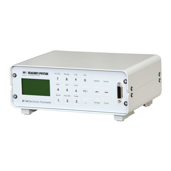
1.2 Instrument Description The EF 14 is easy to operate via the front panel keys and has an easily readable LC display. The alphanumerical display allows user control supported by help texts. - Page 11 AC 90 - 250 V, 50 - 60 Hz, 5 Watt Dimensions: 248 mm (width) x 180 mm (depth) x 100 mm (height) Weight: Approx. 1.5 kg Fig. 1.4.1: EF 14 Front View BA – no.: 100514EBA02 December 9 , 2020 Page 11...
-
Page 12: Ambient Conditions
Electronic Fluxmeter EF 14 1.4 Ambient Conditions Table 1.5.1: Electromagnetic Tolerance (EMV) Immunity from discharge of static electricity: Air discharge: 8 kV based on EN 61000-4-2 Contact discharge: 4 kV Immunity from incident high frequency: 0.15 to 80 MHz 10 V... - Page 13 Electronic Fluxmeter EF 14 0,5 ppm Toxic substances: - SO (rel. moisture 60%, no dew) 0,1 ppm (rel. moisture 60%, no dew) Oscillations: acc. to IEC 68-2-6 10 ... 57 Hz (const. amplitude 0.15 mm), 57 ... 150 Hz (const. acceleration 2g) BA –...
-
Page 14: Taking Into Operation
60 days from date of dispatch. 2.2 Packing for Dispatch If it becomes necessary to send in the EF 14, coils or other accessories for calibration, repair or replacement, inform Magnet-Physik before sending the parts. If an instrument is being sent in for service, the following information is required before the repair can be started: ... -
Page 15: Connecting And Start
If both connections are used at the same time, this will cause faulty measurements. RS 232 plug: The 9 pin Sub-D plug has the connections for RS 232 interface. The EF 14 can be connected to a computer using a so-called Null-Modem-Cable. - Page 16 In this case, press the Reset key to activate the measuring display for the rear input. The word rear behind the coil type shows, that the EF 14 assumes a coil at the rear clamps. To obtain the best results the instrument must warm up for about 20 minutes. The coil plug and the input socket shall have the same temperature to avoid drift due to thermo voltages.
- Page 17 Electronic Fluxmeter EF 14 8. If you proceed with such a test, make sure that a suitable measuring range is selected. Use the range key to set the right measuring range. Caution! The measuring coils must be treated with care. They may be fragile.
-
Page 18: Operation
EF 14 3 Operation The basics for operation of the EF 14 fluxmeter are described here. A description of all the elements of display in measuring operation (standard display) is to be found in chapter 3.1. An overview of the keys and their functions is given in chapter 3.2. -
Page 19: Keypad
Peak Switches the measurement of fast pulses on and off. Drift Starts the automatic drift correction of the EF 14 (only in DC mode). Unit This key is pressed to show the selectable units. The selection available depends on the connected measuring coil. - Page 20 Electronic Fluxmeter EF 14 Escape This key is used to discontinue an input without changing the previously set values. In the single menus it is indicated which keys can be used for inputs. The keys Enter, Mode and Escape are nearly always available. These keys have the following functions: With Enter you complete the current input.
-
Page 21: Device Functions
In all menus the name of the menu is shown in the first line. In the second line follow operation hints. If a menu is entered, the EF 14 stops measuring. Then it is also not possible to read a measured value from the computer interface. -
Page 22: Peak
Fig. 4.2.2: Display of maximum, minimum and difference Pressing Reset sets the readings back to zero. Maximum and minimum are captured with the measuring rate of the EF 14. The Max./Min. function is therefore used to capture exactly the extremes of normal, slowly changing magnetic flux. -
Page 23: Drift
A fluxmeter cannot distinguish between the measured signal and interference. The user must ensure that the drift is accordingly corrected. The automatic drift correction of the EF 14 is a considerable help to the user in this case. The drift correction can also be carried out manually. -
Page 24: Unit
Electronic Fluxmeter EF 14 During the manual drift correction the Reset key can be pressed any time to set the reading back to zero. The reading must not be brought to zero using the arrow key. The arrow keys are only used to stop the change of reading, which means to minimize the drift. -
Page 25: Limit
The EF 14 assigns the required prefix automatically, depending on range and coil constant. µ The required unit is selected with the arrow keys. At the beginning or end of a line the arrow keys are used to move the selection mark into the preceding or following line. -
Page 26: Ac/Dc
In the two lower lines you can see the maximum value that can be measured and which lowest resolution is available. In the 10 Vs range the EF 14 can measure 225.0 mVs at maximum. In the 10 Vs range the resolution is 0.1 µVs. Beside you can see the values in the currently selected unit that correspond to these flux values. - Page 27 the identification number of the coil ID. Due to the high input resistance of the EF 14 of 100 k the resistance of the measuring coil can be often neglected and simply set to zero. If it is not small compared to 100 k, the real resistance must be entered.
- Page 28 If you own measuring coils with bunch or banana plugs or if you design your own measuring coils, you can connect them to the pole clamps on the rear panel of the EF 14. If you prefer a connection to the front side socket, you can find the pole configuration in chapter 7.1.
-
Page 29: Var
If R is entered in the coil menu, the EF 14 should display the real flux for J-compensated surrounding coils for the J coil (B-H): the number of turns as given on the coil label the coil resistance (usually 10 k) -
Page 30: Measuring Data Memory
Fig. 4.10.3: Switching off Var. 4.11 Measuring Data Memory The EF 14 has a data memory that allows to store up to 100 measurements. The stored values remain in the memory even if the instrument is switched off. To store measurements, the instrument must be in measuring operation. Any menu must be active. -
Page 31: Mode Menu
Using Save Coil you can save the data of measuring coils which do not have their own data memory in the EF 14. There are ten memory locations available for this (No. 0 – 9). Before the can data can be stored it must first be entered using the Coil menu. -
Page 32: Information
Fig. 4.4.1: Information menu The Information menu shows the serial number of your EF 14. It must be the same as the serial number than on the label on the rear panel of the instrument. The version number of the instrument software is displayed below the Serial number. -
Page 33: Send Data
The transfer speed (baud rate) for the interface can be set in the RS 232 menu. Make sure that the same baud rate is set on the PC that will communicate with the EF 14. The other communication parameters are fixed: 8 data bits, 1 stop bit, no parity bit. The EF 14 does not support handshaking. -
Page 34: Operating Information
Modern fluxmeters have an input resistance of 10 kΩ or 100 kΩ that is independent of the range. The input resistance of the EF 14 is 100 kΩ. The resistance of many measuring coils is BA – no.: 100514EBA02... -
Page 35: Measurement Of The Maxima Of Magnetizing Impulses
In this case the coil resistance in the coil menu can simply be set to 0. If the coil resistance exceeds about 100 Ω it should be measured and entered. Then the EF 14 calculates the magnetic flux using the formula kΩ... -
Page 36: Ac Measuring Operation
Electronic Fluxmeter EF 14 or for the rise time of the magnetizing pulse at given area turns t The following table shows flux densities and area turns that are typical in magnetizing technology and the resulting limits for rise times: 100 cm²... -
Page 37: Measuring Rate
The functions Max./Min. and Peak can also be used in AC mode. Max./Min. shows the maximum RMS. If the peak function is enabled in AC mode, the EF 14 shows the peak value of the measured flux waveform (and not the peak value of the RMS). The analog peak hold circuit is active but the peak value is not digitally stored. - Page 38 Electronic Fluxmeter EF 14 stored if the EF 14 is switched off. After switching on the instrument is always in normal operation. BA – no.: 100514EBA02 December 9 , 2020 Page 38...
-
Page 39: Remote Control
For nearly every command the EF 14 sends an answer after the command has been executed. Although the EF 14 can store a few commands and execute them one after the other, it is good practice to wait for the answer before the next command is sent. Each answer of the EF 14 ends with a Carriage Return, followed by a Line Feed, as long as anything else is set using the TERM command. -
Page 40: Basic Commands
Read commands start with a question mark, write commands with a # (see above). 6.3.1 Measuring Commands The EF 14 can send single measurements or cyclically a series of measurements. Single measurements can be requested using the ?MEAS command. The cyclic output is controlled by the #NMEAS and #MULTI commands. - Page 41 Only numerical values are sent, without an unit. If required, the unit can be requested using ?UNIT or ?MEAS before. During the fast data mode the EF 14 accepts any other commands despite of #SPEED and #RESET. BA – no.: 100514EBA02...
-
Page 42: Measuring Modes
Electronic Fluxmeter EF 14 6.3.2 Measuring Modes AC or DC mode MODE Write: #MODE 0 for AC #MODE 1 for DC Answer: n = 0, 1 MODE n Read: ?MODE Answer: n = 0, 1 MODE n Max./Min. function Write:... -
Page 43: Instrument Functions
Electronic Fluxmeter EF 14 Answer: n = 0, 1 PEAK n Request of the peak value MPEAK Read: ?MPEAK Answer: MPEAK value unit The command returns an answer only if the Peak function is enabled. As the captured peak value is shown as the main value, it can also be requested using ?MEAS. -
Page 44: Limit Commands
(x = 0...27) UNIT x The settings for other than the listed parameters values are not defined. If a parameter that is not valid for the selected coil is sent, then the EF 14 switches to Vs. Write: Measuring range: x = -4, -5, -6, -7 (for the ranges... -
Page 45: Coil Data Commands
EF 14 exchanges the values. The unit needs not to be sent in the write command. The EF 14 expects the values in the actual basic unit without prefix (e.g. in T, not in mT; to set 1 mT send 0.001). - Page 46 COIL x Read: ?COIL Answer: (x = 0...6) COIL x For compatibility with the EF 5, the EF 14 accepts instead of the command COIL as well the command DEVICE. Coil constant CONST Write: #CONST x x: numerical value 0.000001 ≤ x ≤ 90000000...
-
Page 47: Interface Commands
Read: ?TERM Answer: x = 0, 1 TERM x Sets all user settings, which remain stored when the EF 14 is switched off, back to default values. Write only (#CLR), no parameter The default settings are: Coil: Field Coil Unit: Range: Max./Min. - Page 48 Electronic Fluxmeter EF 14 Terminator Carriage Return and Line Feed Instrument status, Read only (?STAT), the following answers can appear: STAT The instrument is not yet ready for measurement. STAT WAIT Drift function is running. STAT DRIFT The instrument cannot send a measurement, e.g. if a STAT INACT menu is activated in manual operation.
-
Page 49: Pin Assignments Of Plugs And Sockets
Electronic Fluxmeter EF 14 7 Pin Assignments of Plugs and Sockets 7.1 Measuring Coil Connections Important! Only one measuring coil must be connected at one time, either to the socket on the front panel or to the clamps on the rear panel. If both connections are used at the same time, this will cause faulty measurements. -
Page 50: Pole Clamps On The Rear Panel
The RS 232 interface can be fully operated by connecting only the following 3 wires: TxD, RxD and digital ground. TxD of the EF 14 must be connected to the RxD pin on the computer side. RxD of the EF 14 must be connected to the TxD pin on the computer side. A null-modem cable can be used. -
Page 51: Multi-Functional Socket
Electronic Fluxmeter EF 14 7.3 Multi-functional Socket Table 7.3.1: Assignments of the 25-pole Sub-D socket Function Low limit relay, normally open Low limit relay, center contact Low limit relay, normally closed High limit relay, normally open High limit relay, center contact... -
Page 52: Limit Relays
7.3.3 Analog Outputs The analog output of the EF 14 is a real analog, real-time output. The main analog output can be accessed on pin 18. It is scaled in Vs, the coil resistance is not taken into account. - Page 53 Electronic Fluxmeter EF 14 EF 14 to low sensitivity data acquisition systems. The voltage range for a valid output is limited to about ±4.9 V. The auxiliary output can have a considerable offset voltage of several millivolts. Therefore it is recommended to measure the offset voltage during a reset and subtract it from the voltage that is obtained during the measurement.
-
Page 54: Maintenance
The checks shall be periodically repeated and documented. 8.2 Checking for Damage The EF 14 and all accessories must be checked once a month for damages. If any of the components, in particular the instrument housing or a measuring coil are damaged, the device must only be used if it has been cleared for operation by an authorized person. -
Page 55: Taking Out Of Operation
Measure: Make sure that the input connector of the EF 14 and the plug of the coil have the same temperature. Check if the coil wire is insulated from ground, shield or other voltage potentials. Check the measuring coil with an Ohmmeter for wire failure.
Need help?
Do you have a question about the EF 14 and is the answer not in the manual?
Questions and answers