
Subscribe to Our Youtube Channel
Related Manuals for Magnet-physik FH 54


Summary of Contents for Magnet-physik FH 54
- Page 1 Emil-Hoffmann-Str. 3 50996 Cologne Germany Operating Instructions FH 54 Gauss-/Teslameter Preserve for future application! BA - Nr.: 2000540EBA01...
- Page 2 If you face any problems while working with the equipment or the operating instructions or if you have any proposals for improvements please do not hesitate to contact us. Purpose The operating instructions give a survey about the application and functionality of the FH 54. Gauss-/Teslameter Target Group In the following chapters the user of the devicet will find all necessary information regarding handling and operation.
- Page 3 • We also state that the content of these Instructions is not part of a previous or existing agreement, undertaking, or legal relationship, and is not intended to amend the same. All obligations of MAGNET-PHYSIK result from the applicable warranty: These contractual warranty provisions are neither extended nor limited by statements in these instructions.
-
Page 4: Table Of Contents
Gauss- / Teslameter FH 54 Table of Contents General Information ....................6 Safety Instructions ....................6 Intended Purpose ....................6 Sources of Danger ....................7 Authorized Operator .................... 7 Safety Measures at Place of Installation .............. 8 Safeguard Installations ..................8 Emergency Measures ................... - Page 5 ONDITIONS 2 : E (EMV) ..............10 ABLE LECTROMAGNETIC OLERANCE List of Illustrations . 1 : G FH 54 .................... 13 AUSS ESLAMETER . 2 : M NK 1 ................14 AGNETIC SHIELDING CHAMBER . 3: P ..............26 ROBE ORIENTATION FOR POSITIVE READING .
-
Page 6: General Information
FH 54 1 General Information The FH 54 is a handheld instrument for measuring the magnetic field strength H in Ampere per Meter (A/m) and the magnetic flux density or induction B in Tesla (T) or Gauss (G). Particular features of the FH 54 are high accuracy, easy handling and a multitude of functions. -
Page 7: Sources Of Danger
FH 54 1.3 Sources of Danger The field strength meter FH 54 is operated with battery power or with a special mains power supply. At this point, for reasons of work-place safety and accident prevention the sources of danger emanating from such a device will be especially pointed out. The respective instructions to the operator and owner of the field strength meter are to be strictly adhered to. -
Page 8: Safety Measures At Place Of Installation
Gauss- / Teslameter FH 54 1.5 Safety Measures at Place of Installation No special safety measures are necessary. 1.6 Safeguard Installations The device does not have any special safeguard installations as safety concerns have been considered in construction. A potential danger only arises if the device is used against its intended purpose of operation or safety regulations are disregarded. -
Page 9: Transport And Installation
If the device has been damaged in transit, make sure the forwarder and insurance are informed. Inform Magnet-Physik of the same. If there are parts or accessories missing, let Magnet-Physik know immediately. Magnet-Physik cannot accept responsibility for any missing parts if not informed within 60 days from date of dispatch. -
Page 10: Table 2 : Electromagnetic Tolerance (Emv)
Gauss- / Teslameter FH 54 Relative humidity: - for operation Class 3K3 according to EN 50178 5 % to 85 % (indoor), no dew, 1 g/m to 25 g/m - for storage and transport Class 1K3 according to EN 50178... -
Page 11: Introduction
− High Field Probes to 30 T Full-Scale Range. − High Sensitivity Probes – 30 µT to 300 µT Full-Scale Ranges. If you have just received your new FH 54, please proceed to the next chapter and become familiar with the installation instructions. Complete and detailed instrument operational information is contained in chapter functions. -
Page 12: Description
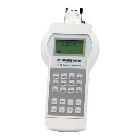
The difference from the setpoint or the relative reading appears in the top display line. In the following figure, the front side of the field strength meter FH 54 is shown. The plug on the upper side is used for probe connection. - Page 13 Gauss- / Teslameter FH 54 Fig. 1 : Gauss-/Teslameter FH 54 BA - Nr.: 2000540EBA01 , 24 , 2019 Page 13 EPTEMBER...
-
Page 14: Operation
(Interface, analog output, power supply) 4. Push the Power On key for minimum one second. The LCD will display FH 54 and then the display will return to the state it was in before being switched off. For best results, the instrument and probe should warm up for at least 5 minutes before zeroing the probe, and at least 30 minutes for rated accuracy. -
Page 15: Standard Display
Gauss- / Teslameter FH 54 automatic ranging). Set the display for DC. Finally, since orientation of the probe is very selective, press the Max./Min. key once. This will capture additionally the highest reading. Caution! Care must be exercised when handling the probe. The tip of the probe is very fragile. - Page 16 Switches Filter on and off. Unit The FH 54 can display the magnetic flux density (induction) B in Tesla (T) or Gauss (G) or the magnetic field strength H in Ampere per Meter (A/m). By pressing the unit button the user can select between these units.
-
Page 17: Probe Handling
Gauss- / Teslameter FH 54 Reset Works with the Max./Min. and the DC Peak function. Resets the reading back to zero to capture the next reading. Relative This key is used to invoke a small menu that allows to activate or deactivate relative function and to set the relative value. - Page 18 Gauss- / Teslameter FH 54 probe should only be held in place by securing at the handle. The probe stem should never have force applied. Any strain on the ceramic substrate may alter the probe calibration, and excessive force may destroy the Hall sensor.
-
Page 19: Functions
FH 54 5 Functions In the present chapter all functions of the FH 54 are described in detail. The most important functions can be accessed directly over function keys. Some rarely used function can be invoked in a menu. This main menu is accessed with the Mode key. The submenus are selected with the arrow keys (, ) and opened with the Enter key. -
Page 20: Zero
5.6 Unit The FH 54 displays the magnetic flux density (induction) B in Gauss (G) or Tesla (T) or the magnetic field strength H in Ampere per Meter (A/m). With the Unit key you can select the desired unit. -
Page 21: Temp
The FH 54 is no temperature measuring instrument. Do not use the probes for temperature measurement. Extreme temperatures and mechanical stress due to fast temperature changes can alter the calibration or destroy the Hall sensor. -
Page 22: Reset
Gauss- / Teslameter FH 54 5.9 Reset The Reset key is used to set the values captured with Max./Min. or Peak (see below) back to zero. 5.10 Max./Min. If the Max./Min. key is pressed once, the largest value that was measured since the last pressing of Reset is displayed in the center of the second display line. -
Page 23: Field Correction (Menu Function)
This correction can be switched off in the menu Temp. Correction. If a probe is connected to the FH 54, or if the instrument is switched off and on again, all correction functions, that have correction data available, are switched on automatically. - Page 24 Gauss- / Teslameter FH 54 with alkaline batteries. If rechargeable NiCd batteries or other batteries with a lower cell voltage are used, the indicator may not be filled black completely even if the batteries are full. Nevertheless, such batteries can be used.
-
Page 25: Probes
Gauss- / Teslameter FH 54 6 Probes To avoid damage and for best results during use, the probes have a number of handling and accuracy requirements that must be observed. 6.1 Changing Probes To connect the probe, take hold of the probe connector and move it straight into socket. Secure the connector with the two screws. -
Page 26: Probe Operation
6.4 Probe Types Three different standard probe Types are available for the FH 54. They are transverse, axial and surface field probe. The transverse probe has a Hall sensor that is mounted parallel to the probe axis. It measures fields, that are perpendicular to the probe axis. -
Page 27: Fig. 4 : Surface Field Probe
Gauss- / Teslameter FH 54 Hall sensor Transverse probe – top view Measures flux density perpendicular to probe axis Transverse probe – side view The axial probe has a Hall sensor, that is mounted perpendicularly to the probe axis. It measures fields that are parallel to the probe axis. -
Page 28: Probe Sensitivity And Measuring Ranges
High sensitivity probe work in the ranges from 30 µT (300 mG) to 300 µT (3 G). 7. If none of the standard probes matches your configuration, keep in mind that Magnet-Physik also can make customized probes for fulfilling special demands regarding dimensions, temperature range or accuracy. - Page 29 Gauss- / Teslameter FH 54 the condition that exists during factory calibration. The greater the deviation from orthogonality (from right angles in either of three axes), the larger the error of the reading. For example, a 5° variance on any one axis causes a 0.4% error, a 10° misalignment induces a 1.5% error, etc..
-
Page 30: Remote Operation
7 Remote Operation 7.1 Access Rights After switching on, the FH 54 is in LOCAL-Mode. In this mode it can be operated from the keypad. When the serial interface starts to write to the instrument, the access from the keypad is restricted (remote mode). - Page 31 Gauss- / Teslameter FH 54 AUTO Write: #AUTO 0 Auto range off #AUTO 1 Auto range on Answer: #AUTO 0 or 1 Read: ?AUTO Answer: AUTO 0 or 1 ZERO Write: #ZERO 1 Starts the Zero routine without further request...
- Page 32 Gauss- / Teslameter FH 54 LIMU Write: #LIMU n,m,u set upper limit value and switch on function n = 1...7 (range) m = -3000...3000 (digits) u = 0...2 (unit) Answer: LIMU n,m,u Read: ?LIMU Answer: current stting LIML Write: #LIML n,m,u set lower limit value and switch on function n = 1...7 (range)
- Page 33 Gauss- / Teslameter FH 54 Write: #MAX 2 Show Max/Min #MAX 1 Show Max #MAX 0 Answer: MAX 0, MAX 1 or MAX 2 Read: ?MAX Answer: MAX 0, MAX 1 or MAX 2 MMAX Read only: ?MMAX Read the Max value Answer: digits and unit, e.g..
- Page 34 Gauss- / Teslameter FH 54 CTEMP Write: #CTEMP 1 Temperature correction on #CTEMP 0 Temperature correction off Answer: CTEMP 0 or CTEMP 1 Error message, if a probe without temperature sensor is connected Read: ?CTEMP Answer: CTEMP 0 (off) or CTEMP 1 (on)
-
Page 35: Maintenance
The checks shall be periodically repeated and documented. 8.2 Checking for Damage The FH 54 and all accessories must be checked once a month for damages. If any of the components, in particular the instrument housing, a probe or an optional line power supply (AC adapter) are damaged, the equipment must only be used if it has been cleared for operation by an authorized person. -
Page 36: Connectors
Analog output - center connector Ground – Connector shielding 8.5.3 Serial Interface RS 232 C / Limit Relays Output The serial interface is a standard feature of the FH 54. The relay output is available as an option. BA - Nr.: 2000540EBA01... - Page 37 Gauss- / Teslameter FH 54 Pin assignment of the DB 9 connector (relay output): DESCRIPTION Relay 1 Normally closed contact RS 232 RS 232 Relay 2 Normally closed contact RS 232 Relay 1 Normally open contact Relay 1 Center contact...
-
Page 38: Connector For Optional Power Supply
Switch off the device. Unplug the probe, the interface cable and the AC adapter if applicable. You should remove the batteries from the FH 54 if the device will not be used for a longer time. This will avoid damage due to leaking batteries. Put the device and the probe into the storage case.
Need help?
Do you have a question about the FH 54 and is the answer not in the manual?
Questions and answers