Advertisement
Quick Links
English
Diagram Reference
Components and Beeps
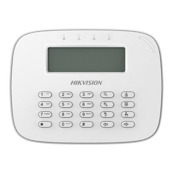
Alarm Keypad
1
Indicator
Product Information
COPYRIGHT ©2018 Hangzhou Hikvision Digital Technology
Co., Ltd.
ALL RIGHTS RESERVED.
Any and all information, including, among others, wordings,
pictures, graphs are the properties of Hangzhou Hikvision
Digital Technology Co., Ltd. or its subsidiaries (hereinafter
referred to be "Hikvision"). This user manual (hereinafter
Key
referred to be "the Manual") cannot be reproduced,
changed, translated, or distributed, partially or wholly, by
any means, without the prior written permission of
Hikvision. Unless otherwise stipulated, Hikvision does not
Beeps
make any warranties, guarantees or representations,
One Beep
express or implied, regarding to the Manual.
Two Beeps
Five Beeps
About this Manual
Continuous Beeping For Two Seconds
This Manual is applicable to Alarm Keypad.
Slowly Continuous Beeps
The Manual includes instructions for using and managing
Rapidly Continuous Beeps
the product. Pictures, charts, images and all other
Rapid Beeps
information hereinafter are for description and explanation
Three Long Beeps and Two Short Beeps
only. The information contained in the Manual is subject to
Three Beeps
change, without notice, due to firmware updates or other
Keypad Address Settings
reasons. Please find the latest version in the company
2
website (http://overseas.hikvision.com/en/).
Configure the address via DIP switch of the keypad before powering
Please use this user manual under the guidance of
on the system. The address should be in the range of 0 to 31. The
professionals.
binary value shown in the diagram is 00111, which means the decimal
value is 7. So the address of the keypad is 7.
Trademarks Acknowledgement and other
Keypad Wiring and Installation
Hikvision's trademarks and logos are the properties of
3
Hikvision in various jurisdictions. Other trademarks and
a. Dimension
logos mentioned below are the properties of their
b. Disassemble the keypad
Loosen the screw, and pry the gap of the edge with a straight screw
respective owners.
driver to disassemble the keypad. Remove the rear panel.
This product and - if applicable - the supplied
c. Wiring
Route the cables through the cable hole of the rear panel, and connect
accessories too are marked with "CE" and comply
the cables to the corresponding terminals.
therefore with the applicable harmonized European
If you need to route the bottom of
standards listed under the RE Directive 2014/53/EU,
the panel, remove the sheet of the
the EMC Directive 2014/30/EU, the RoHS Directive
side opening.
2011/65/EU.
d. Install Keypad
1. Secure the mounting plate on the gang box/wall with supplied
The Input voltage should meet both the SELV (Safety
screws.
Extra Low Voltage) and the Limited Power Source
2. Fasten the keypad body on the plate.
according to the IEC60950-1 standard. Please refer
3. Tighten the screw on the buttom to fix the keypad on the mounting
to technical specifications for detailed information.
plate and complete the installation.
2012/19/EU (WEEE directive): Products marked
Keypad Operation Commands
4
with this symbol cannot be disposed of as unsorted
municipal waste in the European Union. For proper
Function
recycling, return this product to your local supplier
upon the purchase of equivalent new equipment, or
Programming/
dispose of it at designated collection points. For
Editing Password
more information see: www.recyclethis.info
Legal Disclaimer
TO THE MAXIMUM EXTENT PERMITTED BY APPLICABLE LAW,
THE PRODUCT DESCRIBED, WITH ITS HARDWARE, SOFTWARE
AND FIRMWARE, IS PROVIDED "AS IS", WITH ALL FAULTS AND
Testing
ERRORS, AND HIKVISION MAKES NO WARRANTIES, EXPRESS
OR IMPLIED, INCLUDING WITHOUT LIMITATION,
MERCHANTABILITY, SATISFACTORY QUALITY, FITNESS FOR A
Arming/Disarming
PARTICULAR PURPOSE, AND NON-INFRINGEMENT OF THIRD
PARTY. IN NO EVENT WILL HIKVISION, ITS DIRECTORS,
Clearing Alarm
OFFICERS, EMPLOYEES, OR AGENTS BE LIABLE TO YOU FOR
ANY SPECIAL, CONSEQUENTIAL, INCIDENTAL, OR INDIRECT
Keyfob
DAMAGES, INCLUDING, AMONG OTHERS, DAMAGES FOR
LOSS OF BUSINESS PROFITS, BUSINESS INTERRUPTION, OR
LOSS OF DATA OR
Bypass
DOCUMENTATION, IN CONNECTION WITH THE USE OF THIS
PRODUCT, EVEN IF HIKVISION HAS BEEN ADVISED OF THE
POSSIBILITY OF SUCH DAMAGES.
Keypad Settings
REGARDING TO THE PRODUCT WITH INTERNET ACCESS, THE
USE OF PRODUCT SHALL BE WHOLLY AT YOUR OWN RISKS.
HIKVISION SHALL NOT TAKE ANY RESPONSIBILITES FOR
Specification
ABNORMAL OPERATION, PRIVACY LEAKAGE OR OTHER
DAMAGES RESULTING FROM CYBER ATTACK, HACKER
ATTACK, VIRUS INSPECTION, OR OTHER INTERNET SECURITY
Numeric Key
RISKS; HOWEVER, HIKVISION WILL PROVIDE TIMELY
Function Key
Indicator
TECHNICAL SUPPORT IF REQUIRED.
Screen
SURVEILLANCE LAWS VARY BY JURISDICTION. PLEASE CHECK
Input
Output
ALL RELEVANT LAWS IN YOUR JURISDICTION BEFORE USING
Keyfob
THIS PRODUCT IN ORDER TO ENSURE THAT YOUR USE
Card Reading
Tamper Switch
CONFORMS THE APPLICABLE LAW. HIKVISION SHALL NOT BE
RS-485 Interface
Current & Power
LIABLE IN THE EVENT THAT THIS PRODUCT IS USED WITH
Consumption
ILLEGITIMATE PURPOSES.
Operation
Temperature
IN THE EVENT OF ANY CONFLICTS BETWEEN THIS MANUAL
Operation Humidity
AND THE APPLICABLE LAW, THE LATER PREVAILS.
Weight
UD12183B
Solid Green: No Zone Fault in Operation Mode
Solid Red: Zone Fault in Operation Mode
Set
Flashed Green: Not in the Operation Mode
Fault
Solid Orange: System Fault
Off: No Fault
Solid Green: All Enabled Channels Connected Normally
Network
Off: Part of or All Enabled Channels Connected Abnormally
Armed/Disarmed
Solid Blue: Armed
Off: Disarmed
Flashed Red: Alarm Occurred
Alarm
Solid Red: Tamper Alarm
Off: No Alarm
Query
Project
Bypass
Scoll Up
One-Push
Scoll Down
Fire
Panic
to Arm
Pressing keys/command timed out or too long.
Successful operation/Report uploaded.
Failed operation/Failed to upload the report in 60s.
Fault Prompt.
Entry/Exit Delay, more than 10s.
Entry/Exit Delay, less than 10s.
Zone Alarm/keypad not registered.
Keypad tampered.
Keypad registered.
The keypad functions vary
depending on the model of
device.
It is required to insert the screw for tamper alarm.
Description
Command
Control Panel Programming 【Installer Password】【*】【0】【#】
Exit Operation
【*】【#】
【Administrator(Operator 001) Password】【*】【0】【#】
【User No. (3digits)】【#】
Administrator Password
【New Password】【#】
【New Password】【#】
Testing
【Installer Password】【*】【6】【0】【#】
Exiting Testing
【Installer Password】【*】【6】【2】【#】
【Password】【*】【6】【1】【#】
Alarm Center Testing
Project Mode
【Password】【Project】【9】【0】【n】【#】
Exiting Project Mode
【*】【#】
Normal (Away) Arming
【Password】【#】
/Disarming
Instant Arming
【Password】【*】【7】【#】
Stay Arming
【Password】【*】【4】【#】
Clearing Under Arming
【Password】【*】【1】【#】
Status
Add Keyfob
【Password】【*】【9】【1】【Keyfob No.】【sub-system No.】【#】
Delete Appointed Keyfob
【Password】【*】【9】【0】【Keyfob No.】【#】
or【Password】【*】【9】【0】【#】+ press the keyfob
Delete All Keyfobs
【Password】【*】【9】【2】【#】
【Password】【Bypass】【n】【n】【n】【#】
Bypass Zone(n)
【Bypass】【n】【n】【n】【#】
nnn is the zone No.
Enabling/Disabling Keypad
【*】【5】【1】【#】
Tone
Enabling/Disabling Fault
【*】【5】【6】【#】
Prompt
【*】【5】【2】【n】【n】【n】【#】
LCD Backlight Control
nnn is LCD bright duration.
LCD Backlight Disabling
【*】【8】【#】
DS-PK-L
DS-PK-LR
DS-PK-LRT
DS-PK-LRTE
12 keys: 0 to 9,*,#
8 keys: Project/Query/Bypass/On-push to arm/Fire/Panic/Scroll Up/Scroll Down
Fault (Orange), Network (Green), Alarm (Red), Armed/Disarmed (Blue),Set (Red/Green Dual Color)
LCD
N/A
N/A
N/A
2 Alarm Inputs
N/A
N/A
N/A
1 Relay Output
N/A
Two-Way Keyfob
Two-way Keyfob
Two-way Keyfob
N/A
N/A
Supported
Supported
1
1
12 VDC/ 0.15 A
1.8 W
-10 ℃ to+55 ℃
10% to 90%
272 g (0.60 lb)
1
3
a
164.13 mm
30.96 mm
c
Control Panel
2.2K
EOL
D- D+ 12V GND
N.O
N.C
NO/
COM
Z1
GND
Z2
D- D+ 12V
GND
NC
3
b
11 mm
5-
3.7
90 mm
d
GANGBOX MOUNTING
WALL MOUNTING
2
E.G
1 2 3 4 5
low
high
BIN=00111
DEC=7
ADD=7
Advertisement

Subscribe to Our Youtube Channel
Related Manuals for HIKVISION DS-PK-L


Summary of Contents for HIKVISION DS-PK-L
- Page 1 Bypass Zone(n) 【Bypass】【n】【n】【n】【#】 DOCUMENTATION, IN CONNECTION WITH THE USE OF THIS nnn is the zone No. Enabling/Disabling Keypad 【*】【5】【1】【#】 PRODUCT, EVEN IF HIKVISION HAS BEEN ADVISED OF THE Tone Enabling/Disabling Fault POSSIBILITY OF SUCH DAMAGES. 【*】【5】【6】【#】 WALL MOUNTING Keypad Settings...
- Page 2 +54 9 341 6799822 rosarioseguridadok Rosario Seguridad +54 9 341 6708000 ventas@rosarioseguridad.com.ar Rosario Seguridad +54 9 341 6591429 Avenida Presidente Perón 3998 - Rosario - Santa Fe - Argentina www.rosarioseguridad.com.ar...
Need help?
Do you have a question about the DS-PK-L and is the answer not in the manual?
Questions and answers