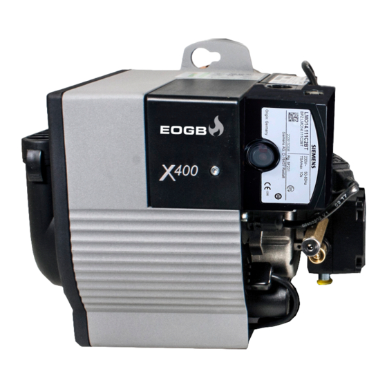
EOGB X400 Instruction Manual
Oil burner
Hide thumbs
Also See for X400:
- Instruction manual (21 pages) ,
- Instruction manual (44 pages) ,
- Instruction manual (20 pages)
Advertisement
INSTRUCTION MANUAL FOR OIL BURNER MODELS
X400
14-36 kW
October 2020 Technical
Amendment
The following amendment provides technical changes to the X-Series Installation
manual and only effects the standard X400 burner unit only.
This amendment covers recent technical changes from the Danfoss OBC81 control
box to the Siemens LMO14.
If you have any further questions regarding this amendment or any other technical
matter relating to our X-Series burners, then please feel free to contact EOGB on
01480 477066 or email technical@eogb.co.uk
I
Amendment 1
21-10-2020
Advertisement
Table of Contents

Related Manuals for EOGB X400


Summary of Contents for EOGB X400
- Page 1 This amendment covers recent technical changes from the Danfoss OBC81 control box to the Siemens LMO14. If you have any further questions regarding this amendment or any other technical matter relating to our X-Series burners, then please feel free to contact EOGB on 01480 477066 or email technical@eogb.co.uk Amendment 1...
-
Page 2: Technical Description Of The Burner
Technical description of the burner Technical description of the burner Technical data X400 X500 X600 Burner operation mode One Stage 14-36 34-62 50-80 Heat output Kg/hr 1.2-3 2.83-5.15 4.23-8.45 Working temperature °C min./max. 0-40 Weight (burner only) 9.3kg Kerosene Maximum viscosity 5.5 cst @ 20°C Suitable for bio blends < B10... -
Page 3: Electrical System
7.2.2 X400 & X500 Electrical wiring (No 7 pin plug) If fitting the X400 or X500 then before carrying out any elec- trical wiring, the electronics cover must be removed (see Fig 14 & 15) Fig. 14 Fig. - Page 4 Electrical System 7.2.3 Worcester Boiler Harness Electrical Wiring 7.2.4 X500 & X600 wiring (with 7 pin plug) If the X-Series has been supplied with a 7 pin plug, then With many Worcester boilers, the wiring harness will have 6 please follow the below wiring diagram. (Fig. 18) wires in total.
- Page 5 Burner Operation and Commissioning Burner Start Cycle Normal Burner Cycle ◄ Thermostat ► Motor ► Transformer ► Solenoid Valve ◄ 11/12 Flame Signal Lockout indicator Pre-ignition/Purge time 15 sec (LMO) 13 sec (OBC). Stray light monitoring Time in seconds Lockout safety time 10 sec Post-ignition time 15 sec.
-
Page 6: Maintenance & Service
If further problems are encountered then please contact EOGB Energy Products Ltd for advice. Technical helpline – Tel: 01480 477066 option 2. -
Page 7: Spare Parts List
Spare parts list 10.1 X400 Spare parts list Amendment 1 21-10-2020... - Page 8 Spare parts list 10.1 X400 Spare parts list Amendment 1 21-10-2020...
- Page 9 Please note that the oil nozzle size should be determined by the E80-0401 Side cover X400 boiler/appliance manufacturer. If in doubt the please contact E80-500-005-120-00 Neoprene sponge sealing cord 650mm EOGB for further information on nozzle sizing or refer to Table E required Page 21 E80-1302 Electronics cover X400 E80-302-006-112-01...
- Page 10 EOGB Energy Products Ltd, 5 Howard Road, Eaton Socon, St Neots, Cambridgeshire PE19 8ET Tel: 01480 477066 Fax: 01480 477022 Email:sales@eogb.co.uk www.eogb.co.uk www.youtube.com/EOGBenergyproducts @EOGBburners...
Need help?
Do you have a question about the X400 and is the answer not in the manual?
Questions and answers