Table of Contents
Advertisement
INSTRUCTION MANUAL FOR OIL BURNER MODELS
ONE STAGE, GAS OIL, KEROSENE AND B10 BIOFUEL BURNERS
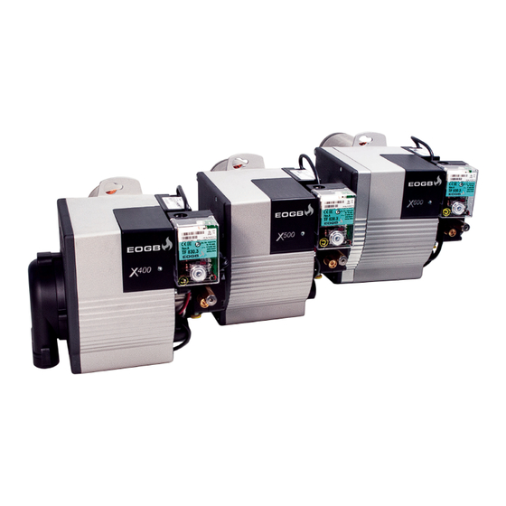
The X-series range is available in three models, with outputs ranging from 14 to 80
kW, They can be configured for conventional or ducted air inlets to suit installations
in domestic. commercial and light industrial premises. All the models are approved
by the EN267 European Standard and conform to European Directives for EMC, Low
Voltage, Machinery and Boiler Efficiency.
X400
14-36 kW
X500
34-62 kW
X600
50-80 kW
Revision 1
01/01/16
Advertisement
Table of Contents

Subscribe to Our Youtube Channel
Related Manuals for EOGB X500


Summary of Contents for EOGB X500
- Page 1 INSTRUCTION MANUAL FOR OIL BURNER MODELS X400 14-36 kW X500 34-62 kW X600 50-80 kW ONE STAGE, GAS OIL, KEROSENE AND B10 BIOFUEL BURNERS The X-series range is available in three models, with outputs ranging from 14 to 80 kW, They can be configured for conventional or ducted air inlets to suit installations in domestic.
-
Page 2: Table Of Contents
Electrical system Notes on safety for the electrical wiring 7.2.1 Electrical wiring 7.2.2 X400 & X500 electrical wiring (no 7 pin plug) 7.2.3 Worcester boiler harness electrical wiring 7.2.4 X500 & X600 wiring (with 7 pin plug) Burner opeartion and commissioning... -
Page 3: Declaration
EOGB Energy Products Ltd 5 Howard Road, Eaton Socon, St Neots, Cambs, PE19 8ET Manufacture the following products; X400, X500 & X600 Oil fired burners In accordance with the following Directives and Normative documents: Machines Directive 98/37/EEC Efficiency Directive 92/42/EEC... -
Page 4: Information & General Warnings
Other symbols owner or user, or to another system. If the manual is lost or damaged, another copy can be requested from EOGB on ENVIRONMENTAL PROTECTION request. This symbol gives indications for the use of the machine with respect for the environment. -
Page 5: Guarantee And Responsibility
If in any doubt please contact EOGB for further advice. If any EOGB burners are used with fuel with a bio content >10%then Failure to observe the information given in this manual, the components within the hydraulic circuit may be affected and operating negligence, incorrect installation and carry- are not covered under warranty. -
Page 6: Information And General Instructions
In no event will EOGB (and its subsidiaries) be responsible ble with biofuels. For all installations, there must be a good quality... -
Page 7: Safety And Prevention
Safety and prevention Safety and prevention Introduction The burners have been designed and built in compliance with the type and pressure of the fuel, the voltage and frequency of current regulations and directives, applying the known technical the electrical power supply, the minimum and maximum deliveries rules of safety and envisaging all the potential danger situations. -
Page 8: Technical Description Of The Burner
Technical description of the burner Technical description of the burner Technical data X400 X500 X600 Burner operation mode One Stage 14-36 34-62 50-80 Heat output Kg/hr 1.2-3 2.83-5.15 4.23-8.45 Working temperature °C min./max. 0-40 Weight (burner only) 9.3kg Kerosene Maximum viscosity 5.5 cst @ 20°C Suitable for bio blends < B10... -
Page 9: Burner Components
1 x Balanced flue air intake conversion kit (X400 only) specification of the biofuel may be requested. 1 x Balanced flue rubber adaptor 60mm to 70mm (X400 and X500 only) 1 x High output air damper (X400 only) 1 x Low output air damper (X500 only) -
Page 10: Burner Dimensions
Technical description of the burner Burner dimensions Additional air intake option X400 Narrow Balanced Version Version ø50mm ø60mm X500 Air intake options X600 X500 X600 ø60mm ø70mm Burner dimensions (mm) Aø root Aø max Jø Kø X400 161 194 138 297 90 125-150 10... -
Page 11: Firing Rates
1013 mbar (approx. 0 m pressure in the combustion chamber. WARNING above sea level) and with the combustion head adjusted to factory settings X400 X500 X600 Kg/h Fig. 3 Revision 1 01/01/16... -
Page 12: Installation
D - Burner Voltage E - Motor Phase Serial Number F & G - Minimum & maximum flow rate Batch No H - Serial number www.eogb.co.uk T 01480 477066 I - Batch number WARRANTY INVALID IF REMOVED Fig. 4 Revision 1... -
Page 13: Installer/Service Notes For The Use Of Gas Oil With Bio Blends Up To 10% Where Gas Oil Use Is Permitted By The Appliance Manufacturer
The burner hydraulic components and flexible oil oil and biofuel blends are in accordance with EOGB’s spec- lines must be suitable for biofuel use (check with EOGB if ifications (please refer to the chapters “Technical Data” and in doubt). EOGB have carefully chosen the specification “Guidance for the use of biofuel blends up to 10%”... -
Page 14: Boiler Fixing
Installation Boiler fixing 5.6.1 Mounting onto the appliance 5.6.2 Service mounting position The burner is mounted onto the appliance by means of a For ease of servicing and access to the burner components removable 6-bolt flange. the burner has, on the bottom face, a keyhole cut-out. This allows the burner to be hung from the mounting flange in a The gasket needs to be put in place before the flange is more convenient position. -
Page 15: Air Intake Assembly
X400. see Fig. 7 • The intake tube can be up to 6 metres in length. The X500 and X600 both have the BF air intake fitted as Length is reduced if there are bends in the intake section. -
Page 16: Oil Pump
Pressure adjuster WARNING Nozzle outlet 1/8” Vacuum gauge port 1/8” Please contact EOGB for further information. Return outlet port 1/4” Suction inlet port 1/4” Revision 1 01/01/16... -
Page 17: Oil Supply
(60 µ for gas oil and 15 µ for kerosene) are CAUTION used to protect the burner pump and nozzle from contamination. In case of biodiesel use, pay attention to install compatible filters. (Contact EOGB for more infor- mation) Revision 1 01/01/16... - Page 18 Oil Supply Table. D - 1 Pipe Suction Lift With De-Aerator Maximum Allowable Pipe Run From Tank To De-Aerator (metres) Flue Flow-rate 2.5 (kg/h) 5.0 (kg/h) 10 (kg/h) 10 (kg/h) 8mm inside dia. pipe HEAD (metres) 6mm inside dia. pipe (8mm O.D copper) (10mm O.D copper) -0.5 -1.0...
-
Page 19: Electrical System
Electrical System Electrical system Notes on safety for the electrical wiring • The electrical wiring must be carried out with the electrical supply disconnected. • Electrical wiring must be carried out by qualified personnel and in compliance with the regulations currently in force in the country of destination. -
Page 20: Electrical Wiring
7.2.2 X400 & X500 Electrical wiring (No 7 pin plug) If fitting the X400 or X500 then before carrying out any elec- trical wiring, the electronics cover must be removed (see Fig 18 & 19) Fig. 14 Fig. -
Page 21: Worcester Boiler Harness Electrical Wiring
7.2.3 Worcester Boiler Harness Electrical Wiring 7.2.4 X500 & X600 wiring (with 7 pin plug) If the X-Series has been supplied with a 7 pin plug, then With many Worcester boilers, the wiring harness will have 6 please follow the below wiring diagram. -
Page 22: Burner Opeartion And Commissioning
A CO level should be kept to a minimum and ideally less than 100ppm but if in doubt then Nozzles installation contact EOGB. The burner complies with the emission requirements of the EN 267 standard. In order to guarantee that emissions do not vary, recom-... - Page 23 33.2-40.6 Low/High 1.20 100-150 40-49 Kerosene **1.25 100-150 42.4-51.8 S / H High 1.35 100-150 46.5-56.9 1.50 100-145 52.5-62 X500 0.65 210-250 34-38 0.75 180-250 35.41.1 0.85 180-250 39.3-46.4 Gas Oil S / H High 1.00 180-250 44.2-52.1 1.10 180-250 50.4-59.4...
-
Page 24: Low & High Output Air Damper Adjustment
(85,000 BTU). If you require a higher output, then fit the HIGH output air adjuster. The X500 comes fitted with the HIGH output air adjuster, this is to be used with a burner output of over 40kW (136,500 BTU). If you require a lower output then fit the LOW output air adjuster. -
Page 25: Electrode Settings
X400 Fig. 26 Fig. 27 Please note the position of the electrode block should be located at approximately 11:00 o’clock (see Fig 26) X500 & X600 Only Fig. 28 Fig. 29 Model X400 43.0 X500... -
Page 26: Burner Start Cycle
Burner Operation and Commissioning Burner Start Cycle Normal Burner Cycle Thermostat Motor Transformer Solenoid Valve Flame Lockout indicator Pre-ignition/purge time 12 sec. Stray light monitoring Time in seconds Lockout safety time 10 sec Post-ignition time 20 sec. Burner lockout due to no flame establishment Thermostat Motor Transformer... -
Page 27: Maintenance & Service
WARNING In case of use of a different Biofuel then please con- Clean the combustion head in the fuel exit area, on the tact EOGB for further information (a fuel specifica- diffuser disc. tion may be requested) Burner... -
Page 28: Fault Finding
10 secs photocell to light the flame, Check combustion settings, consult EOGB for further information If the burner still establishes a flame then The burner Solenoid stem is letting by Disconnect solenoid lead and re-test. - Page 29 Remove photocell and ensure that it is sulphur fuel, reset combustion with a Co2 covered and not exposed to any light, reset % of around 12-12.5 % or contact EOGB for Low sulphur fuel burner and once the burner establishes...
-
Page 30: Commissioning Report Sheet
Serial No. Nozzle angle & Pattern Settings CO² Flue Draft mbar Air damper setting O² Head setting (X500/600 only) Smoke Flue Gas Temp Nett °C Efficiency Pump pressure Psi/Bar Please note: This report sheet must be completed by the Commissioning Engineer and the book is to be left with the appliance. -
Page 31: Service Records
Model Nozzle size Serial No. Nozzle angle & Pattern Settings CO² Flue Draft mbar Air damper setting O² Head setting (X500/600 only) Smoke Flue Gas Temp Nett °C Efficiency Pump pressure Psi/Bar Service Notes Service Date Next Service due Burner... - Page 32 Model Nozzle size Serial No. Nozzle angle & Pattern Settings CO² Flue Draft mbar Air damper setting O² Head setting (X500/600 only) Smoke Flue Gas Temp Nett °C Efficiency Pump pressure Psi/Bar Service Notes Service Date Next Service due Burner...
- Page 33 Model Nozzle size Serial No. Nozzle angle & Pattern Settings CO² Flue Draft mbar Air damper setting O² Head setting (X500/600 only) Smoke Flue Gas Temp Nett °C Efficiency Pump pressure Psi/Bar Service Notes Service Date Next Service due Burner...
-
Page 34: Spare Parts List
Spare parts list 10.1 X400 Spare parts list Revision 1 01/01/16... - Page 35 Spare parts list 10.1 X400 Spare parts list Revision 1 01/01/16...
- Page 36 Please note that the oil nozzle size should be determined by the E80-0401 Side cover X400 boiler/appliance manufacturer. If in doubt the please contact E80-500-005-120-00 Neoprene sponge sealing cord 650mm EOGB for further information on nozzle sizing or refer to Table E required Page 21 E80-1302 Electronics cover X400 E80-302-006-112-01...
- Page 37 Spare parts list 10.2 X500 Spare parts list Revision 1 01/01/16...
- Page 38 Spare parts list 10.2 X500 Spare parts list 33 34 Revision 1 01/01/16...
- Page 39 Please note that the oil nozzle size should be determined by the boiler/appliance manufacturer. If in doubt the please contact E80-0007 Air damper (high output) + seal EOGB for further information on nozzle sizing or refer to Table E Page 21 E80-0402 Side cover X500/600...
- Page 40 Spare parts list 10.3 X600 Spare parts list Revision 1 01/01/16...
- Page 41 Spare parts list 10.3 X600 Spare parts list Revision 1 01/01/16...
- Page 42 Please note that the oil nozzle size should be determined by the boiler/appliance manufacturer. If in doubt the please contact E80-500-005-120-00 Neoprene sponge sealing cord 650mm EOGB for further information on nozzle sizing or refer to Table E required Page 21 E80-001-007-100-00...
- Page 43 Notes Revision 1 01/01/16...
- Page 44 EOGB Energy Products Ltd, 5 Howard Road, Eaton Socon, St Neots, Cambridgeshire PE19 8ET Tel: 01480 477066 Fax: 01480 477022 Email:sales@eogb.co.uk www.eogb.co.uk www.youtube.com/EOGBenergyproducts @EOGBburners Revision 1 01/01/16...
Need help?
Do you have a question about the X500 and is the answer not in the manual?
Questions and answers