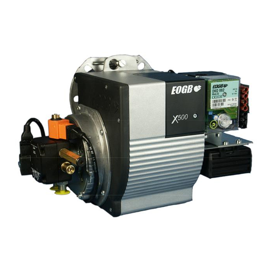
Summary of Contents for EOGB X500-2
- Page 1 INSTRUCTION MANUAL FOR OIL BURNER MODELS X500-2 – Low voltage – 12v dc – Brushed motor E90-803-001-005-01 – Rev 4 - 1 -...
-
Page 2: Table Of Contents
Contents Technical specifications Technical data ....................3 Working field .....................3 Dimensions ......................4 Head and electrode settings ................5 Components ......................6 Burner installation Mounting onto the appliance................7 Electrical connection ..................7 Fuel supply ......................7 Air supply ......................7 Burner operation Before start-up ....................8 Start-up procedure ....................8 Normal operating mode ..................9 Burner servicing Combustion head ....................10... -
Page 3: Technical Specifications
Technical specifications Technical Data Burner output Min kW Max kW Fuel flow rate Min Kg/hr 2.88 Max Kg/hr Fuel Kerosene Max viscosity 5.5 cst @ 20 Gas oil Electrical supply Input 12 volt dc Motor 12 volt dc brushed Ignition unit 24 volt dc Start current 21 amps... -
Page 4: Dimensions
Technical specifications Dimensions (mm) 125-150 E90-803-001-005-01 – Rev 4 - 4 -... -
Page 5: Head And Electrode Settings
Technical specifications Head and electrode settings Model X500-2 3.5 E90-803-001-005-01 – Rev 4 - 5 -... -
Page 6: Components
Technical specifications Components 1 Blast tube 2 Mounting flange 3 Air intake 4 Fanhouse 5 Air adjuster Lockout reset button Control box Photocell (hidden) Ignition unit Motor 24v – 12v converter H.T. leads (hidden) Ignition electrodes Electrode holder Nozzle Nozzle assembly Brakeplate E90-803-001-005-01 –... -
Page 7: Burner Installation
Burner installation Mounting onto the appliance The burner is mounted onto the appliance by means of a removable 6-bolt flange. The gasket needs to be put in place before the flange is fixed onto the appliance. The burner tube is then inserted through the centre hole after fitting the O-ring over the the blast tube. -
Page 8: Burner Operation
Burner operation Before start-up Check that the correct nozzle is fitted. Reference should be made to the instructions of the appliance manufacturers. If the burner is firing Kerosene the nozzle must be sized for a maximum pump pressure of 10 bar (145 psi). If Gas Oil is being used then a smaller nozzle must be selected to allow a pump pressure of approx 14 bar (200 psi). -
Page 9: Normal Operating Mode
Normal operating mode Check the oil pressure on the gauge and adjust if necessary for the required burner output. From a suitable test point on the boiler, or in the flue, a smoke reading should be taken to ensure clean smoke- free combustion. -
Page 10: Burner Servicing
Burner servicing Combustion head For ease of servicing and access to the burner components the burner has, on the bottom face, a keyhole cut-out. This allows the burner to be hung from the mounting flange in a more convenient position. Keyhole slot After loosening the fixing bolt the burner can be extracted from the flange, turned around and then the keyhole can be located... - Page 11 It is important that the nozzle holder is prevented from rotating by use of a second spanner while unscrewing the nozzle Once the burner has been re-fitted a smoke check and combustion analysis must be carried out. If necessary, the position of the brakeplate/nozzle assembly can be altered within the blast Brakeplate position...
-
Page 12: Oil Pump
Fuel pump type Danfoss BFP11 R3 Technical data Oil Viscosity range: 1.3 – 12.0 cSt Pressure range: 7 – 15 bar Oil temperature: -10 - +70ºC 1 - Nozzle port 1/8” 2 - Vacuum gauge port 1/8” 3 - Suction line port 1/4” 4 - Return line port 1/4”... - Page 13 Fuel pump type Danfoss BFP…. Function As the oil pump turns it draws oil from the suction line connection S, through the filter H and into the suction side of the gear set C. Any suction generated before the gear set can be measured with an appropriate vacuum gauge at connection V.
-
Page 14: Oil Supply Line Tables
Oil supply line tables One-pipe system Two-pipe system Kerosene 2.15 mm s (cSt) Kerosene 2.15mm s (cSt) Ø5 Ø6 Ø5 Ø6 Ø8 Ø6 Ø8 Ø10 Ø4 -0.0 -0.5 -1.0 -1.5 -2.0 -2.5 -3.0 -3.5 Nozzle capacity 5.0 kg/h 10.0 kg/h -4.0 Gas oil 6.00 mm s (cSt) -
Page 15: Nozzle Table
Nozzle table E90-803-001-005-01 – Rev 4 - 15 -... -
Page 16: Fault Finding Table
Fault finding Below is a list of some scenarios that may lead to a failure causing the burner to go into lockout mode. There are also some relevant tests and solutions to hopefully overcome any problem that may occur. Push the reset button to re-start the burner. If the burner then functions correctly the control has simply responded to a temporary fault. - Page 17 Please note: The information given above is provided to assist the engineer with any problems they may encounter. This is not a definitive list. If further problems are encountered then please contact EOGB Energy Products Ltd for advice. Technical helpline – Tel: 01480-477066 E90-803-001-005-01 –...
-
Page 18: Commissioning Report Sheet
Please note: This report sheet must be completed by the Commissioning Engineer and the book is to be left with the appliance. E90-803-001-005-01 – Rev 4 - 18 -... -
Page 19: Burner Service Record
Burner Service record The details below are to be completed by the Service Engineer for each service carried out. Date Details of service Signature E90-803-001-005-01 – Rev 4 - 19 -... -
Page 20: Notes
Notes EOGB Energy Products Ltd 5 Howard Road, Eaton Socon, St Neots, Cambs, PE19 8ET Telephone: 01480 477066 Facsimile: 01480 477022 Website: www.eogb.co.uk E-mail: sales@eogb.co.uk E90-803-001-005-01 – Rev 4 - 20 -...


Need help?
Do you have a question about the X500-2 and is the answer not in the manual?
Questions and answers