
Subscribe to Our Youtube Channel
Related Manuals for EOGB BT14


Summary of Contents for EOGB BT14
- Page 1 INSTRUCTION MANUAL FOR OIL BURNER MODELS BT14 24v DC ONE STAGE, GAS OIL, KEROSENE AND B10 BIOFUEL BURNERS The BT14 is available in 24v DC, with outputs ranging from 85 to 170 kW, Revision 1 22-03-17...
-
Page 2: Table Of Contents
Contents Page Contents Information & general warnings Information about this instruction manual and general warnings 2.1.1 Introduction 2.1.2 General dangers 2.1.3 Danger: Live components Guarantee and responsibility Guidance for the use of biofuel blends up to 10% where gas oil use is permitted by the appliance manufacturer 2.3.1 Information and general instructions... -
Page 3: Information & General Warnings
Other symbols owner or user, or to another system. If the manual is lost or damaged, another copy can be requested from EOGB on ENVIRONMENTAL PROTECTION request. This symbol gives indications for the use of the machine with respect for the environment. -
Page 4: Guarantee And Responsibility
If in any doubt please contact EOGB for further advice. If any EOGB burners are used with fuel with a bio content >10%then Failure to observe the information given in this manual, the components within the hydraulic circuit may be affected and operating negligence, incorrect installation and carry- are not covered under warranty. -
Page 5: Information And General Instructions
In no event will EOGB (and its subsidiaries) be responsible ble with biofuels. For all installations, there must be a good quality... -
Page 6: Safety And Prevention
Safety and prevention Safety and prevention Introduction The burners have been designed and built in compliance with the type and pressure of the fuel, the voltage and frequency of current regulations and directives, applying the known technical the electrical power supply, the minimum and maximum deliveries rules of safety and envisaging all the potential danger situations. -
Page 7: Technical Description Of The Burner
Technical description of the burner Technical data Burner operation mode One Stage 85 - 170 Heat output Kg/hr 7.17 - 14.35 Working temperature °C min./max. 0-40 Weight (boxed) Kerosene Maximum viscosity 5.5 cst @ 20°C Suitable for bio blends < B10 Gas Oil Viscosity 4 - 6 (@ 20°C) for light oil models / 1.5 - 6 (@ 20°C) for kerosene... -
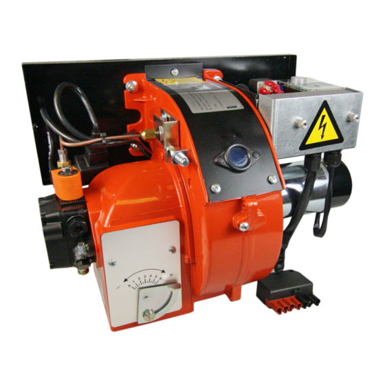
Page 8: Burner Components / Dimensions
Technical description of the burner Burner Components / Dimensions Sight Glass Reset Button Solenoid Valve Motor Air Regulation Blast Tube Mounting Gasket Mounting Flange Flame Disk Adjustment Oil Pump Suction Return Ø Ø Revision 1 22-03-17... -
Page 9: Burner Mounting
Installation Burner Mounting Fitting The Burner to the Boiler/Application The burner is fitted with a sliding attachment flange on the combustion head. All the components supplied must be mounted following the burner instructions Sheet metal ring Rope cord Mounting gasket Mounting flange Fig. -
Page 10: Hydraulic Connections
Installation Installation Hydraulic Connections The pipes that connect the tank to the burner should be air tight. We recommend the use of copper or steel pipes of a adequate diameter (see charts below). Isolation valves should be fitted at the end of rigid pipelines. Fit the filter to the suction pipeline after the isolation valve. -
Page 11: Notes On Safety For The Installation
D - Burner Voltage E - Motor Phase Serial Number F & G - Minimum & maximum flow rate Batch No H - Serial number www.eogb.co.uk T 01480 477066 I - Batch number WARRANTY INVALID IF REMOVED Fig. 4 Revision 1... -
Page 12: Installer/Service Notes For The Use Of Gas Oil With Bio Blends Up To 10% Where Gas Oil Use Is Permitted By The Appliance Manufacturer
The burner hydraulic components and flexible oil oil and biofuel blends are in accordance with EOGB’s spec- lines must be suitable for biofuel use (check with EOGB if ifications (please refer to the chapters “Technical Data” and in doubt). EOGB have carefully chosen the specification “Guidance for the use of biofuel blends up to 10%”... -
Page 13: Electrical System
Electrical System Electrical system Notes on safety for the electrical wiring • The electrical wiring must be carried out with the electrical supply disconnected. • Electrical wiring must be carried out by qualified personnel and in compliance with the regulations currently in force in the country of destination. -
Page 14: Electrical Wiring
The electrical wiring carried out by the installer must be in compliance with the rules in force in the country. The section of the conductors must be at least 1mm2 (unless requested otherwise by local standards and legislation). Wiring Diagram for BT14 (7pin connection) External Components... - Page 15 Electrical System Wiring Diagram for BT14 (No 7pin connection) External Components Components B - 24v DC Supply Satronic DKO992-24 Control box TC - Control thermostat PE - Photocell TA - Transformer M - Motor Fig. 7 V1 - Solenoid Valve...
-
Page 16: Burner Opeartion And Commissioning
A CO level should be kept to a minimum and Preparations for Start up ideally less than 100ppm but if in doubt then contact EOGB. Ensure that the correct size nozzle has been fitted for the application, The table below (see fig 13) shows the deliv- ery rates in kg/hr of light oil against nozzle size and pump pressure (Normally 12 bar). -
Page 17: Pump Pressure
Burner Operation and Commissioning Pump pressure Burner Head Adjustment The pump pressure when it leaves the factory (unless other The burner is fitted with adjustable screw which regulates wise specified) will be set to approx 9 bar. Pump pressure the flame disk position, this adjustment allows for fine tuning should then be set to appliance manufacturer’s recom- of the combustion by increasing or decreasing the air pas- mendations depending on what nozzle size is recommend-... -
Page 18: Electrode Settings
The position of the electrodes can be critical to ensure the ignition spark is generated in the correct place. To ensure a safe reliable ignition of the fuel, please check your electrode settings using the below diagrams. WARNING Fig. 14 Fig. 15 Model BT14 Revision 1 22-03-17... -
Page 19: Maintenance & Service
WARNING In case of use of a different Biofuel then please con- Clean the combustion head in the fuel exit area, on the tact EOGB for further information (a fuel specifica- diffuser disc. tion may be requested) Burner... -
Page 20: Fault Finding
Maintenance / Service Fault finding Should a fault occur, the following fault find flow chart should offer guidance on resolving the fault. Test Have you got a 24v (or 12v if using a 12v version) signal on the incoming Positive Negative on L1 &... - Page 21 Do you get the same _ _ _ _ . Problem resolved lockout code? Follow instructions for the different fault code If a fault code appears that is not listed then please contact EOGB Energy products on 01480 477066 Revision 1 22-03-17...
- Page 22 Revision 1 22-03-17...
- Page 23 Revision 1 22-03-17...
- Page 24 Revision 1 22-03-17...
- Page 25 Revision 1 22-03-17...
- Page 26 Revision 1 22-03-17...
- Page 27 Revision 1 22-03-17...
- Page 28 Revision 1 22-03-17...
- Page 29 Revision 1 22-03-17...
- Page 30 If further problems are encountered then please or scan this QR code to take you directly to the YouTube site contact EOGB Energy Products Ltd for advice. Technical helpline – Tel: 01480 477066 option 2 Email - technical@eogb.co.uk Web - www.eogb.co.uk...
-
Page 31: Commissioning Report Sheet
Maintenance / Service Commissioning Report Commissioning Report Sheet Commissioning Engineer Address OFTEC number Date of Commissioning Site address Appliance Make Model Serial No. Output (kW/BTU) Fuel Type of Flue Burner Model Nozzle size Serial No. Nozzle angle & Pattern Settings CO²... -
Page 32: Service Records
Maintenance / Service Service Records Service Date Next Service due Burner Model Nozzle size Serial No. Nozzle angle & Pattern Settings CO² Flue Draft mbar Air damper setting O² Head setting (X500/600 only) Smoke Flue Gas Temp Nett °C Efficiency Pump pressure Psi/Bar Service Notes... - Page 33 Maintenance / Service Service Date Next Service due Burner Model Nozzle size Serial No. Nozzle angle & Pattern Settings CO² Flue Draft mbar Air damper setting O² Head setting (X500/600 only) Smoke Flue Gas Temp Nett °C Efficiency Pump pressure Psi/Bar Service Notes Service Date...
- Page 34 Maintenance / Service Service Date Next Service due Burner Model Nozzle size Serial No. Nozzle angle & Pattern Settings CO² Flue Draft mbar Air damper setting O² Head setting (X500/600 only) Smoke Flue Gas Temp Nett °C Efficiency Pump pressure Psi/Bar Service Notes Service Date...
- Page 35 EOGB Energy Products Ltd, 5 Howard Road, Eaton Socon, St Neots, Cambridgeshire PE19 8ET Tel: 01480 477066 Fax: 01480 477022 Email:sales@eogb.co.uk www.eogb.co.uk www.youtube.com/EOGBenergyproducts @EOGBburners Revision 1 22-03-17...
Need help?
Do you have a question about the BT14 and is the answer not in the manual?
Questions and answers