
Related Manuals for Promac JDT-4024


Summary of Contents for Promac JDT-4024
- Page 1 05-2019 Drill Press JDT-4024 Bohrmaschinen Perceuses France Schweiz / Suisse JPW (TOOL) AG TOOL FRANCE SARL Ackerstrasse 45, CH-8610 Uster, 9 Rue des Pyrénées, 91090 LISSES, France www.promac.fr Switzerland www.promac.ch...
- Page 2 CE-Conformity Declara on CE-Konformitätserklärung Déclara on de Conformité CE Product / Produkt / Produit: JDT-4024 Drill Press / Bohrmaschinen / Perceuses Brand / Marke / Marque: PROMAC Manufacturer / Hersteller / Fabricant: TOOL FRANCE SARL 9 Rue des Pyrénées, 91090 LISSES, France We hereby declare that this product complies with the regula Wir erklären hiermit, dass dieses Produkt der folgenden Richtlinie entspricht...
-
Page 3: Table Of Contents
Total Operation Manual page Contents 1. Main use and features of the machine 2. Main technical data 3. Brief description of the driving system and its structure 4. Electrical system 5. Lubrication and coolant system 6. Hoisting and installation 7. Use and operation of the machine 8. - Page 4 Total Operation Manual page Dear end-user, Thank you very much for choosing our products. Please let us have the model of your machine, series number, as well as the name, address and correspondence method of your company in order to facilitate us to let you have a good service. Important notice: 1.
-
Page 5: Main Use And Features Of The Machine
Total Operation Manual page 1.Main use and features of the machine: JDT series vertical drilling machines are our new products designed and developed by our-self based on our accumulated experience in so many years in this field. It is really a multi-function universal machine which could be widely used for small and middle sizes of work pieces for drilling, spot facing, reaming, tapping, Milling Plane, slot-milling, angular mill etc. -
Page 6: Main Technical Data
Total Operation Manual page 2. Main technical data: 2.1 Main technical data Name of the items Unit Data Max. dr i lling di a meter ( s teel) Max. tapping diameter (steel) Distance between spindle center line to the center line of column Max. -
Page 7: Brief Description Of The Driving System And Its Structure
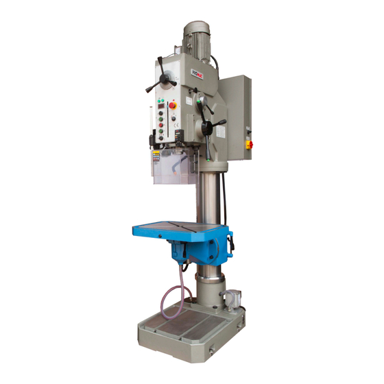
Total Operation Manual page 2.2 For the machine appearance and its main technical data, see diagram 1. 3. Brief description of the driving system and its structure: The machine consists of spindle box, column, machine base, worktable and its bracket, electric cabinet, coolant device and machine accessories, total seven component parts. - Page 9 Total 26 Operation Manual page 6 drawing 2 picture of transmission...
- Page 10 Total 26 Operation Manual page 7 list of gear, worm wheel,worm and rack table(1) Number on the drawing Part drawing 11016/ 12013/ 12011/ 12012/ 32004/ 310013/ 32003/ 32030/ 32041/ ZY5050 ZY5050 ZY5050 ZY5050 ZY5040 ZY5050 Number of teeth and starts Module 1.75 Direction of...
- Page 11 Total 26 Operation Manual page 8 4.1 list of gear, worm wheel,worm and rack table(1) Number on the drawing Part drawing 32052/ 32002/ 32003/ZY5 32001/ 32009/ZY5 32005/ZY5 32006/ZY5 32002/ZY5 32001/ZY5 ZY5050 040A-2 040A-2 040A-2 040A-1 040A-2 040A-2 Number of teeth and starts Module 1.75...
- Page 12 Total 26 Operation Manual page 9 drawing 3 picture of rolling bearing...
- Page 13 Total Operation Manual page Roller bearing table Table (2) Model Name Specification Q’ty Accuracy GB276;7000102 Deep groove ball bearing 15×32×8 GB301;8104 Flat thrust ball bearing 20×35×10 GB276;104 Deep groove ball bearing 20×42×12 GB276;1180909K Sealed deep groove ball bearing 45×68×12 GB276;D7000110 Deep groove ball bearing 50×80×10 GB301;8110...
-
Page 14: Electrical System
Total Operation Manual page 4. Electrical system 4.1 Brief description The machine with foreign advanced single chip and superior quality electric element is controlled by electric system, the software system not only realize all kinds movement control ,but also has many protective function with catenation, the capability of this system is very good ,and the movement of this system is jarless and reliable. - Page 15 Total 26 Operation Manual page 12 spindle motor M1 limit switch SQ2 digital play handle button SB4 operation panel electric box B1 mm/r limit switch SQ3 pump button SX2 limit switch SQ1 power supply button QS1 handle button SB4 illuminative lamp EL1 handle button SB4 limit switch SQ6 operation panel...
- Page 16 Total Operation Manual page 4.5 Emergency stop operation: If emergency stop is necessary during operation, press emergency push button SB1,so the machine is completely stopped .After eliminating the breakdown ,release the lock of the push button then restart the machine. 4.6 Coolant pump Revolving the switch of coolant pump right, then the coolant pump is moving and working with the spindle.
- Page 18 FU21(1A) brown black High-speed signal blue switch for spindle motor emergency stop reverse rotate brown black limit position (below) for feed blue brown black limit position(above) for feed blue start/stop for feed out/in for tapping tapping switch for spindle stop rotate in clockwise FU22(3A)
- Page 19 Total Operation Manual page Electric components list: Table (3) Name Specification Q’ty Remark Code of elements Breaker GV2-ME10 Breaker GV2-ME03 Breaker GV2-ME06 Instruction switch JCH13-20 SX1,2 Selection switch C2SS2-10B-10 CE4T-10R-02 Emergency stop button SB2,5 Push button GQ22-11E/G/24V/S Push button GQ22-11E/W/24V/S Push button GQ22-11E/R/24V/S Single lamp...
-
Page 20: Lubrication And Coolant System
Total Operation Manual page 5.Lubrication and coolant system: 5.1 Lubrication system: Parts and bearings inside of the spindle box are all automatically lubricated. Oil level shall be a little bit higher than the centerline of the oil window when you fill lubrication oil. Too much oil filling will cause overflowing. - Page 21 Total 26 Original Instruction page 18 drawing 6 picture of lubrication Chart of lubrication position No.of lubrication Grease designation lubrication period lubrication position position Grease up once every 3 oil pool of spindle box month Surface of main spindle Oiling once for each shift ISO VG33 machinery oil sleeve Oiling once for each shift...
- Page 22 Total 26 Operation Manual page 19 mm/r Warning Please put oil when the machine is stopped.The oil lever shall not exceed the red dot for centerline of the oil window. Otherwise the oil would be overflowing from horizontal shaft! drawing 7. picture of hoisting...
- Page 23 Total Operation Manual page When the foundation is completely dry, the machine could be laid down on the adjustable pad. Concrete could be filled when screw bolts are placed. Fastening screw bolts after concrete is completely dry. Leveling the machine first, required tolerance should not be over 0.04/1000mm both in horizontal and cross plane.
- Page 24 Total 26 Operation Manual page 21 mm/r Warning Please put oil when the machine is stopped.The oil lever shall not exceed the red dot for centerline of the oil window. Otherwise the oil would be overflowing from horizontal shaft! 1600x1000 drawing 8 picture of installation of machine...
- Page 25 Total Operation Manual page In case too tight mesh between tool shank and spindle taper and the tool cutter could not fall down after several strokes, then you have to use the normal way by using a taper wedge to dismounting the tool cutter.
- Page 26 Total Operation Manual page Manual micro feed: Spindle micro feed needs two steps. First, put the feed rate lever( 5 )in the “idle” position. Secondly, push button ( SB4 ), then push up the micro feed hand wheel( 3 ) and make sure that the clutch is engaged, now the micro feed hand wheel could be turned and micro feed of the spindle works.
-
Page 27: Machine Adjustment
Total Operation Manual page 7.8 Adjustment of worktable position: Symbols multi-use and convenience of the machine also reflects multi function of its worktable. Except its normal manual and auto up and down function, it can also be turned around the table itself, around the column and tilt in ±45°in horizontal position. Operation method for the table tilting Using a special tool to take out the taper pin and loosening four screw nuts on the bracket and manually turn the worktable to the required position then fastening the four screw nuts,... -
Page 28: Machine Use And Maintenance
Total Operation Manual page 9 Machine use and maintenance: 9.1 Before running the machine, carefully read the Operation Manual first, fully understand the structure of the machine and its performance and needs to familiar with locations for all levers and buttons. 9.2 Lubrication of the machine is very important. -
Page 29: Machine Accessories
Total Operation Manual page 9.10 Do not extend spindle quill too much, instead, a proper working table height is suggested .Clean the spindle taper hole and tool taper shank first before tool mounting. Unqualified or rusted or damaged taper shank is forbidden to use. 9.11 Dry agent inside of the electric box and regularly removing dustiness are necessary. - Page 30 Total Packing list page Case No.: 1/1 Dimension ( L ×W × H): 110×67 ×225 CM Gross weight:660kg Net weight: 630kg Name Specification and marks Q’ty Remark Machine 1 piece Drill chuck with lever 1-13: GB6087 1 piece Drill chuck adaptor 1 piece 4-3: JB3477 1 piece...
- Page 31 Parts Breakdown For JDT-4024 Drill Press Drawing (1) 157. · 1 " 叶 砬 啊 � � ^ � i� 斤 " "'-.. I趴 上 、 � 忑 12 , 、 「 、 O' 2 父 !Il 1' 5 3 4 , \...
- Page 32 Part List for JDT-4024 DRILL PRESS Part no. Descirption Size Qty. 1 JDT4024-1-001 Knurled screw7bolt 2 JDT4024-1-002 Knurled knob 3 JDT4024-1-003 Taper pins 3x26 JDT4024-1-004-1 Scaled screw JDT4024-1-004-2 Retaining ring 5 JDT4024-1-005 Scaled nut 6 JDT4024-1-006 Support for7The vernier 7 JDT4024-1-007...
- Page 33 Part List for JDT-4024 DRILL PRESS Part no. Descirption Size Qty. JDT4024-1-036-1 indicator dial JDT4024-1-036-2 Slotted set7screws with cone point M5X12 JDT4024-1-036-3 Positioning screw JDT4024-1-036-4 cylindrical helical compression spring JDT4024-1-036-5 Ball JDT4024-1-037-1 Positioning screw JDT4024-1-037-2 Ball JDT4024-1-037-3 cylindrical helical compression spring...
- Page 34 Part List for JDT-4024 DRILL PRESS Part no. Descirption Size Qty. JDT4024-1-058-1 Stop Pin JDT4024-1-058-2 Hex Nut JDT4024-1-058-3 Flat Washer JDT4024-1-058-4 Slotted set screws with dog point M5X12 JDT4024-1-059-1 Holder JDT4024-1-059-2 cylindrical helical compression spring JDT4024-1-059-3 Slotted7countersunk head screws M4X10...
- Page 35 Part List for JDT-4024 DRILL PRESS Part no. Descirption Size Qty. JDT4024-1-093-1 Gear JDT4024-1-093-2 JDT4024-1-094-1 Gear JDT4024-1-094-2 retaining ring 95 JDT4024-1-095 Deep groove ball bearings 96 JDT4024-1-096 Motor JDT4024-1-097-1 Motor Gear JDT4024-1-097-2 retaining ring JDT4024-1-098-1 Bearing JDT4024-1-098-2 round head screw...
- Page 36 Part List for JDT-4024 DRILL PRESS Part no. Descirption Size Qty. 133 JDT4024-1-133 Round Nut M14X1.5 134 JDT4024-1-134 Tab Washers For Round Nut 135 JDT4024-1-135 Flat bottomed thrust ball bearing 136 JDT4024-1-136 Bearing Seat 137 JDT4024-1-137 O-RING 55X3.1 138 JDT4024-1-138 O-RING 19X2.4...
- Page 37 Part List for JDT-4024 DRILL PRESS Part no. Descirption Size Qty. 177 JDT4024-1-177 retaining ring 178 JDT4024-1-178 Internal Circlips 179 JDT4024-1-179 Adjusting Washer 180 JDT4024-1-180 Deep groove ball bearings 181 JDT4024-1-181 Adjusting Washer 182 JDT4024-1-182 Cross shaft 183 JDT4024-1-183 Deep groove ball bearings...
- Page 38 Parts Breakdown For JDT-4024 Drill Press Drawing (2) 51 , 46 � \;'[0 � 在7 在8 � 、 � 叮 负 ; ._____ 9 /1...
- Page 39 Part List for JDT-4024 DRILL PRESS Part no. Descirption Size Qty. 1 JDT4024-2-01 Base 2 JDT4024-2-02 Cover 3 JDT4024-2-03 Column 4 JDT4024-2-04 Rack 5 JDT4024-2-05 Water strainer 6 JDT4024-2-06 Plate 7 JDT4024-2-07 Slotted countersunk head screw M6X10 8 JDT4024-2-08 Pipe joint...
- Page 40 Part List for JDT-4024 DRILL PRESS Part no. Descirption Size Qty. 50 JDT4024-2-50 Hexagon socket head cap screws M12X30 10 51 JDT4024-2-51 Double end bolt 52 JDT4024-2-52 Main nut for clamping board 53 JDT4024-2-53 Connecting board for bracket 54 JDT4024-2-54...
- Page 41 Les CG peuvent être envoyées sur demande par poste ou par e-mail . TOOL FRANCE SARL se réserve le droit d'effectuer des changements sur le produit et les accessoires à tout moment. TOOL FRANCE SARL 9 Rue des Pyrénées, 91090 LISSES, France www.promac.fr...
Need help?
Do you have a question about the JDT-4024 and is the answer not in the manual?
Questions and answers