
Related Manuals for SPX APV DELTA PR2


Summary of Contents for SPX APV DELTA PR2
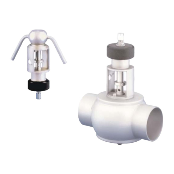
- Page 1 Operating Manual DELTA PR2 Sampling Valve Read and understand this manual prior to operating or servicing this product.
-
Page 5: Table Of Contents
Table of Content Page 1. General Terms 2. Safety Instructions 3. Mode of Operation 4. Auxiliary Equipment 5. Cleaning 6. Installation 6.1 Welding Instructions Maintenance 8. Dimensions / Weights 9. Materials Technical Data Service Instructions 7 - 9 Trouble Shooting Spare Parts Lists PR2 - HF RN 01.143.0... -
Page 7: General Terms
General Terms This operating manual has to be read carefully and observed by the competent operating and maintenance personnel. We have to point out that we will not accept any liability for damage or malfunctions resulting from the non-compliance with this operating manual. -
Page 8: Auxiliary Equipment
Auxiliary Equipment * Valve position indication A switch to signal the limit position of the valve shaft (On/Off) can be mounted in the yoke area (C) if required. * Steam-resistant housing (DN 25) This housing is available for both valve actuations and is welded direct to the tank or pipeline. -
Page 9: Welding Instructions
Welding Instructions - Before welding of the valves, the valve insert must be dismantled from the housing. See to a careful handling to avoid damage. - Welding may only be carried out by certified welders (EN 287-1). (Seam quality EN 25817 "B"). - The welding of the valve housing must be undertaken in such a way that deformation strain cannot be transferred from the outside to the valve body. -
Page 10: Dimensions / Weights
Dimensions / Weights pneumatically actuated design manual design pneumatically actuated design with steam-resistant housing DN 25 37,6 weight in Kg dimensions in mm HF - manual FS - actuated design design inch 1,5” 34,9 38,1 44,4 99,4 2” 47,6 50,8 51,0 107,0 3”... -
Page 11: Materials
Materials housing, housing cover 1.4571 or 1.4404 spring cylinder, yoke, upper part of shaft, operating cam, screws, air connection 1.4301 seals standard design EPDM options HNBR ,FPM, VMQ lower part of shaft PTFE / 25 % glass fiber handle Hostalen Technical Data - max. -
Page 12: Service Instructions
Service Instructions Manual design - PR2 HF The item numbers refer to the spare parts drawing RN 01.143.0. Dismantling from the line system a. Shut off line pressure in the product line. b. Turn handle (8) to the left until the valve is in open position. c. - Page 13 Service Instructions Pneumatically actuated design (PR2-FS-H) The item numbers refer to the spare parts drawing RN 01.146-2. III. Dismantling from the line system a. Shut off line pressure in the product line. b. Remove pneumatic air line. c. Release screw of feedback support and pull off proximity switch.
- Page 14 Service Instructions Pneumatically actuated design (PR2-FS-H) Installation of seals and assembly of valve (PR2-FS-H) a. Slightly grease the shaft seal (3) and O-Ring (9, 19, 15) and place them into the grooves. b. Place the PTFE shaft tip (5.2) on the metal part (5.1) and lock it into place.
-
Page 15: Trouble Shooting
Trouble Shooting Manual design The item numbers refer to the spare parts drawing RN 01.143.0. Failure removal see chapter 11.I. and II. Service Instructions. - Leakage at the sampling connection - turn handle (8) into position "OFF" - replace valve shaft tip (1.2) - Leakage between housing and yoke flange... - Page 16 Phone: +49(0) 23 03/ 108-0 Fax: +49(0) 23 03 / 108-210 For more information about our worldwide locations, approvals, certifications, and local representatives, please visit www.apv.com. Copyright © 2008 SPX Corporation The information contained in this document, including any specifications and other product details, are subject to change without notice.
Need help?
Do you have a question about the APV DELTA PR2 and is the answer not in the manual?
Questions and answers