
Related Manuals for Ingersoll-Rand T480 Series


Summary of Contents for Ingersoll-Rand T480 Series
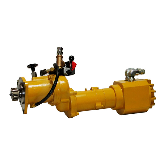
- Page 1 45528270 Edition 1 June 2007 Barring Motor T480 Series Maintenance Information Save These Instructions...
-
Page 2: General Instructions
WARNING Always wear eye protection when operating or performing maintenance on this Barring Motor. Always turn off the air supply and disconnect the air supply hose before installing, removing or adjusting any accessory on this Barring Motor or before performing any maintenance on this Barring Motor. Note: When reading the instructions, refer to exploded diagrams in parts Information Manuals when applicable (see under Related Documentation for form numbers). - Page 3 Disassembly of the Drive Module If the Spindle Planet Gear Bearings (10) must be replaced, press them from the Planet Gears. Refer to drawing 45504115 and associated parts list, for additional Insert a hooked tool into the flange end of the Gear Case and information regarding part numbers and position within the catching the spindle end of the Internal Gear (7), pull it from the assembly.
- Page 4 When grasping a Motor or one of its parts in a vise, always use 8. Lightly coat the Piston Seals (8, 10) with O-ring lubricant, and leather or copper vise jaw covers to protect the surface of the install them in their respective grooves on the Brake Piston (9). part and reduce the likelihood of damage.
- Page 5 Pressing only on the inner race of the Bearing, mount the Rear Place the Gasket (5) on the Offset Gear case, and slide the Spindle Bearing (8) onto the Spindle. assembled Gear Case Cover (14), bearing recess first and seal to Apply lubricant to the gearing and position the Spindle within the the outside, down over the Drive Gear until it contacts the Offset Gear Case (13), making sure the Planet Gears properly engage the...
-
Page 6: Troubleshooting Guide
Assembly of the Pendant and Hose Kit Place the Lock Pin Assembly (18) into the top “OUT” Port of the Drive Housing and tighten to the specified requirements. Refer to drawing 45535762, and associated parts list, for more Place the Elbow (19) into the out Port of the Drive Housing and details on assembly and the associated components. - Page 7 Notes:...
- Page 8 www.irtools.com © 2007 Ingersoll Rand Company...
Need help?
Do you have a question about the T480 Series and is the answer not in the manual?
Questions and answers