Table of Contents
Advertisement
Quick Links
OPERATOR'S MANUAL
INCLUDING: SERVICE KITS, TROUBLESHOOTING, PARTS LIST,
DISASSEMBLY AND REASSEMBLY.
READ THIS MANUAL CAREFULLY BEFORE INSTALLING,
It is the responsibility of the employer to place this information in the hands of the operator. Keep for future reference.
SERVICE KITS
Use only genuine ARO® replacement parts to assure com-
y
patible pressure rating and longest service life.
637489 for general repair of all air motors.
y
GENERAL DESCRIPTION
DO NOT EXCEED MAXIMUM OPERATING
WARNING
PRESSURE AS INDICATED ON PUMP MODEL PLATE.
REFER TO GENERAL INFORMATION SHEET
WARNING
FOR ADDITIONAL SAFETY PRECAUTIONS AND IM-
PORTANT INFORMATION.
This manual only covers the air motor section. It is one of
y
four documents which support an ARO pump. Replace-
ment copies of these forms are available upon request.
Pump Model Operator's Manual.
General Information for Air Operated or Hydraulically
Operated Pumps.
Lower Pump End Operator's Manual.
Air or Hydraulic Motor Operator's Manual.
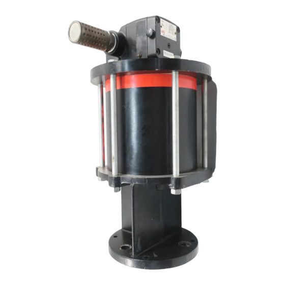
The 8" air motor is a general purpose power unit and is
y
used with many 2-ball, 4-ball, and chop check pumps. It
utilizes tie rod type construction for easy breakdown and
it connects to the various lower ends via tie rods for easy
operation. Consult pump model operator's manual for
specific instructions.
MODEL DESCRIPTION CHART
Air Motor Diameter
08 - 8"
Stroke Length
6 - 6"
Air Motor Base/Rod Combination
0 - Divorced pump base with quick coupled rod connection.
Air Motor Options
01 – Integrated On/Off Valve and Regulator
INGERSOLL RAND COMPANY INC
209 NORTH MAIN STREET – BRYAN, OHIO 43506
(800) 495-0276
FAX (800) 892-6276
arozone.com
8" AIR MOTORS
6" STROKE
Also covers 637489 service kits
OPERATING OR SERVICING THIS EQUIPMENT.
THIS MANUAL COVERS THE FOLLOWING MODELS
AF0860
A F 08 X X – XX
(See Figure 3)
© 2021
CCN 15331390
MODEL
AF0860-01
AF0860
OPERATING AND SAFETY PRECAUTIONS
DO NOT EXCEED MAXIMUM AIR INLET PRESSURE OF
y
120 PSI (8.3 BAR) OR 75 CYCLES PER MINUTE.
High pressure equipment – Always dis-
CAUTION
connect air supply and relieve material pressure be-
fore attempting to service.
A ground lug is located on the air motor. This ground
y
lug allows proper grounding of the pump.
[A]
= Aluminum
[B]
= Buna Nitrile
[Br] = Brass
[Bz] = Bronze
[C]
= Carbon Steel
DISASSEMBLY OF AIR MOTOR
NOTE: All threads are right hand.
1. Force the piston assembly up by pushing the (115) rod
toward the top of the air motor.
2. Remove the (155) muffler/(201) muffler assembly for
ease of disassembly.
3. Remove the four (138) socket head screws from the (140)
head manifold and the one (138) socket head screw form the
(122) head plate. Remove the (140) head manifold by pull-
ing up and outward to remove from tubes (114) and (137).
AF0860-XX
RELEASED:
REVISED:
(REV: F)
AF0860-01
Figure 1
MATERIAL CODE
[D]
= Acetal
[PP] = Polypropylene
[SS]
= Stainless Steel
[Ef]
= Epoxy - Fiberglass Filament Reinforced
[CK] = Ceramic
(continued on page 3)
8-16-10
2-12-21
Advertisement
Table of Contents

Subscribe to Our Youtube Channel
Related Manuals for Ingersoll-Rand AF0860 Series


Summary of Contents for Ingersoll-Rand AF0860 Series
- Page 1 OPERATOR’S MANUAL AF0860-XX INCLUDING: SERVICE KITS, TROUBLESHOOTING, PARTS LIST, RELEASED: 8-16-10 REVISED: 2-12-21 DISASSEMBLY AND REASSEMBLY. (REV: F) 8” AIR MOTORS 6” STROKE Also covers 637489 service kits READ THIS MANUAL CAREFULLY BEFORE INSTALLING, OPERATING OR SERVICING THIS EQUIPMENT. It is the responsibility of the employer to place this information in the hands of the operator. Keep for future reference. THIS MANUAL COVERS THE FOLLOWING MODELS MODEL AF0860...
- Page 2 PARTS LIST / AF0860-XX Item Description (Qty) Part No. [Mtl] 101 Base & Bearing (1) 66525-1 148c 109 Nut (6) Y11-8-C (1/2” - 20) 111 O-Ring (2) Y325-265 (1/8” X 8” OD) 112 Cylinder (1) 96939 [Ef] 143c 113 O-Ring (4) Y325-115 c147 (3/32”...
- Page 3 DISASSEMBLY OF AIR MOTOR (CONT’D) 8. Assemble the six (121) bolts thru the (122) head plate and the (101) base assembly. 4. Remove (141) major gasket from the (140) head manifold. 9. Assemble the six (109) nuts to (121) hex head bolts and 5.
- Page 4 REASSEMBLY OF AIR MOTOR AIR MOTOR BASE AND ROD COMBINATION 28. Loosely install the (114) tube into the bore in the (101) base assembly. 29. Install the (141) manifold gasket into the (140) mani- fold and telescope onto both (114 & 137) tubes until the (113) O-rings are seated.
- Page 5 DIMENSIONAL DATA Dimensions shown are for reference only, they are displayed in inches. (1.62) (2.25) (2.56) (2.75) (1 1/4 - 11 1/2 NPTF-1) MAJOR EXHAUST PORT (1/4-18 NPTF-1) PILOT EXHAUST PORT (7.00) (3.00) (1.99) (3.80) (7.00) (2.50) (3/4-14 NPTF-1) AIR INLET PORT (1/2-14 NPTF-1) (5.68) AIR INLET PORT...
- Page 6 Page 6 of 8 AF0860-XX (en)
- Page 7 AF0860-XX (en) Page 7 of 8...
- Page 8 PN 97999-1472 Page 8 of 8 AF0860-XX (en)
Need help?
Do you have a question about the AF0860 Series and is the answer not in the manual?
Questions and answers