Table of Contents
Advertisement
Quick Links
Bulletin MSG11-5715-616/UK
Operation Manual
Series PID00A-40X
Design >10
Electronics for
Closed Loop Control
Parker Hannifin
Manufacturing Germany GmbH & Co. KG
Industrial Systems Division Europe
Gutenbergstr. 38
41564 Kaarst, Germany
E-mail: isde.kaarst.support@support.parker.com
Copyright © 2021, Parker Hannifin Corp.
Advertisement
Table of Contents

Subscribe to Our Youtube Channel
Related Manuals for Parker PID00A-40X Series


Summary of Contents for Parker PID00A-40X Series
- Page 1 Bulletin MSG11-5715-616/UK Operation Manual Series PID00A-40X Design >10 Electronics for Closed Loop Control Parker Hannifin Manufacturing Germany GmbH & Co. KG Industrial Systems Division Europe Gutenbergstr. 38 41564 Kaarst, Germany E-mail: isde.kaarst.support@support.parker.com Copyright © 2021, Parker Hannifin Corp.
- Page 2 The user must analyze all aspects of the application, follow applicable industry standards, and follow the information concerning the product in the current product catalog and in any other materials provided from Parker or its subsidiaries or authorized distributors.
-
Page 3: Table Of Contents
Guideline for closed loop applications 5.5.1. Application: Closed loop systems for position 5.5.2. Application: Closed loop systems for pressure 5.5.3. Application: Closed loop systems for velocity 5.6. Fade out function 5.7. Error messages Maintenance Trouble-shooting PID00A_10 5715-616 UK.indd 20.05.21 Parker Hannifin Corporation... -
Page 4: Introduction
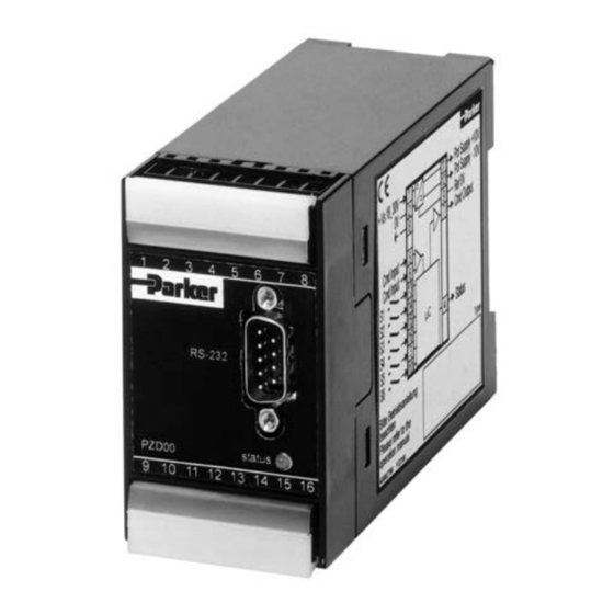
1. Introduction 1.1 Front view / dimensions 1.2 Ordering code Electronic Universal Min/Max Technology Design module adjustment function series closed loop accel/decel ramps control command input controller Code Function Standard Linearization 1.3 Name plate PID00A_10 5715-616 UK.indd 20.05.21 Parker Hannifin Corporation... -
Page 5: Block Diagram
Electronics for Closed Loop Control Operation Manual Series PID00A-40X 1.4 Block diagram 1.5 Characteristics Parker electronic modules PID00A-40* for rail mounting are compact, easy to install and pro- • Extended PID controls vide time-saving wiring by disconnectable ter- • Velocity control with position feedback minals. -
Page 6: Technical Data
Screw terminals 0.2...2.5 mm², disconnectable Cable specification [AWG] 20 overall braid shield Cable length [m] 50 Options Technology function Code1 Software adjustable transfer function with 10 compensation points for linearization of valve behaviour. PID00A_10 5715-616 UK.indd 20.05.21 Parker Hannifin Corporation... -
Page 7: Signal Flow Diagram
Electronics for Closed Loop Control Operation Manual Series PID00A-40X 1.7 Signal flow diagram PID00A_10 5715-616 UK.indd 20.05.21 Parker Hannifin Corporation... -
Page 8: Safety Instructions
Paying This operation manual is valid for module electron- no attention may result in damaging the electron- ics PID00A-40X series. Any use diverging or go- ics or incorporated system parts. ing beyond is deemed to be as not intended. The manufacturer is not liable for warranty claims re- 2.1 Symbols... -
Page 9: Mounting / Installation
The connecting wires have to comply to the fol- lowing specification: Wire type: hookup cable, stranded Cross sections: min. AWG 20/0.5 mm² Wire length: max. 50 m For wire lengths > 50 m consult factory. PID00A_10 5715-616 UK.indd 20.05.21 Parker Hannifin Corporation... -
Page 10: Electrical Interfacing
Each electronics module requires a separate pre-fuse of 0.5 Amp time lag. Non-observance of this instruction may create irreparable damage of electronics resp. incorporated system parts. PID00A_10 5715-616 UK.indd 20.05.21 Parker Hannifin Corporation... - Page 11 Incorrect signal amplitude levels may disturb functionality and may damage the module! Wiring diagram of enable input PID00A_10 5715-616 UK.indd 20.05.21 Parker Hannifin Corporation...
- Page 12 NAMUR is an association of users of The output will switched on when the input process control technology. signal reaches a value of 3.8 mA, it switches PID00A_10 5715-616 UK.indd 20.05.21 Parker Hannifin Corporation...
- Page 13 • feedback signal cable break (not for voltage options / ±20 mA) • command signal cable break (only for option 4...20 mA) • internal processor fault • enable off Wiring diagram of status output PID00A_10 5715-616 UK.indd 20.05.21 Parker Hannifin Corporation...
- Page 14 16, the earth ground connection will be made via ter- lead to permanent damage to the electronics minal 8. The connection has to be shielded. The sen- module. sor type is selectable via software parameter E11. PID00A_10 5715-616 UK.indd 20.05.21 Parker Hannifin Corporation...
- Page 15 Operation Manual Series PID00A-40X Wiring diagram of sensor input 0...±10 V Wiring diagram of sensor input 0...+20 mA / 4...12...20 mA, 3-wire Wiring diagram of sensor input 0...+20 mA / 4...12...20 mA, 2-wire PID00A_10 5715-616 UK.indd 20.05.21 Parker Hannifin Corporation...
- Page 16 Closed loop position control of a hydraulic cyl- forance. for the sake of clarify the appropriate inder, utilizing a proportional directional control illustration is ommitted. valve with integrated electronics (D*FP). Com- mand signal preset using a potentiomater. PID00A_10 5715-616 UK.indd 20.05.21 Parker Hannifin Corporation...
- Page 17 Operation Manual Series PID00A-40X Example 2 Closed loop position control of a hydraulic cylin- der, performed via proportional directional control valve with external electronic (D*FC, D*FS). Com- mand preset via external control signal. PID00A_10 5715-616 UK.indd 20.05.21 Parker Hannifin Corporation...
- Page 18 Operation Manual Series PID00A-40X Example 3 Closed loop pressure control within a hydraulic cylinder, performed utilizing a proportional pres- sure con trol valve with external electronic (RE*W, VMY). Command preset via external control signal. PID00A_10 5715-616 UK.indd 20.05.21 Parker Hannifin Corporation...
- Page 19 Operation Manual Series PID00A-40X Example 4 Closed loop position control of a hydraulic cylin- der, utilizing a proportional directional control valve (D*FB) with external drive electronics PWD00. Command preset via external control signal. PID00A_10 5715-616 UK.indd 20.05.21 Parker Hannifin Corporation...
-
Page 20: Operating Instructions
The PC software can be downloaded free of charge for future use (Floppy disc or Hard drive), output- at www.parker.com/euro_hcd – see page “Sup- ted as a text file for documentation purposes or port" or directly at www.parker.com/propxd. -
Page 21: Program Installation
“ProPxD” program, it should Prior to the updating of older versions these has be deleted by using the Windows® - system con- to be deinstalled via the Windows® Contol Panel. trol feature. PID00A_10 5715-616 UK.indd 20.05.21 Parker Hannifin Corporation... -
Page 22: Software Operating
• The chosen parameters may be optionally stored on the PC via the “File” menu with the menu item “Save as”, data retrieving is always pos- sible via the function “Load out of database” PID00A_10 5715-616 UK.indd 20.05.21 Parker Hannifin Corporation... -
Page 23: Adjustment Parameters
RS-232 interface port via the menu item “Port”. Via the menu item “Load out of database” previously stored parameter sets may be loaded. Information on the technology functions is provided within the help function of the operating software. PID00A_10 5715-616 UK.indd 20.05.21 Parker Hannifin Corporation... - Page 24 1 = ±10 V 2 = ±20 mA 3 = 4-20 mA bipolar option command output – 1 = ±10 V 12 = 4-20 mA unipolar 15 = 0-10 V unipolar 16 = ±50 mA PID00A_10 5715-616 UK.indd 20.05.21 Parker Hannifin Corporation...
- Page 25 Adjustment of the operating mode for the command cable break detec- tion. cable break detection To turn on resp. off of the cable break detection for the command signal command at a selected command signal option of 4...20mA.. PID00A_10 5715-616 UK.indd 20.05.21 Parker Hannifin Corporation...
- Page 26 MAX velocity mm/s 10000 10000 0 = y=X (synchronous) set value output function – 0 = y=x 1 = y=1-x (reversal) MIN fadeout position -120.0 +120.0 -120.0 MAX fadeout position -120.0 +120.0 +120.0 PID00A_10 5715-616 UK.indd 20.05.21 Parker Hannifin Corporation...
- Page 27 Adjustment of the MIN switching point for the ramped set value reduction to zero. MIN fadeout position To automate motion sequences. Adjustment of the MAX switching point for the ramped set value reduc- tion to zero. MAX fadeout position To automate motion sequences. PID00A_10 5715-616 UK.indd 20.05.21 Parker Hannifin Corporation...
-
Page 28: Guideline For Closed Loop Applications
D), each with a user adjustable coefficient. the highest value that does not result in sustained The user software provides therefore the parame- oscillations of the drive position. ters P16 (P), P17 (I) and P18 (D). PID00A_10 5715-616 UK.indd 20.05.21 Parker Hannifin Corporation... - Page 29 This should be fol- lowed by returning of the drive to the start po- sition, where the dwell in position may also be evaluated. PID00A_10 5715-616 UK.indd 20.05.21 Parker Hannifin Corporation...
- Page 30 This parameter is only active if a window (> 0) is defined via P26. PID00A_10 5715-616 UK.indd 20.05.21 Parker Hannifin Corporation...
- Page 31 There is a mode of mechanical vibration created by the mass of the load and the compressibility of the hydraulic fluid in the whole system. This frequency is often surprisingly low when using long stroke cylinders. PID00A_10 5715-616 UK.indd 20.05.21 Parker Hannifin Corporation...
-
Page 32: Application: Closed Loop Systems For Pressure
A too low a value of P17 causes low frequency oscillations, with a too higher value the required pressure may be reached too slowly. PID00A_10 5715-616 UK.indd 20.05.21 Parker Hannifin Corporation... - Page 33 This should be followed by re- turning of the pressue to the start value, where the stationary value may also be evaluated. PID00A_10 5715-616 UK.indd 20.05.21 Parker Hannifin Corporation...
- Page 34 In this case the integrator operates only within this window. Se- lect this option via parameter P26. Step increas- es of the window size will eliminate the oscillation. PID00A_10 5715-616 UK.indd 20.05.21 Parker Hannifin Corporation...
- Page 35 1000 Hz. This rate is fast enough to have negligible effect in almost all hydraulic applica- tions, but it does set an absolute limit on the re- sponse of the system. PID00A_10 5715-616 UK.indd 20.05.21 Parker Hannifin Corporation...
-
Page 36: Application: Closed Loop Systems For Velocity
Too low a value of P17 caus- es low frequency oscillations, with too high a value the required pressure may be reached too slowly. PID00A_10 5715-616 UK.indd 20.05.21 Parker Hannifin Corporation... - Page 37 This should be followed by returning of the drive with a differ- ent velocity to evaluate also the opposite drive direction. PID00A_10 5715-616 UK.indd 20.05.21 Parker Hannifin Corporation...
- Page 38 P-gain is set too high. The electronic provides a “Window” feature (sometimes called “in-position-window”) to solve this problem. Select the parameter P26. Small step adjustments increasing the window size, sufficient to stop the slow oscillations. PID00A_10 5715-616 UK.indd 20.05.21 Parker Hannifin Corporation...
- Page 39 There is a mode of instability caused by a combination of the mass of the load and the compressibility of the hydraulic fluid in the system. This frequency is often surprisingly low when using long stroke cylinders. PID00A_10 5715-616 UK.indd 20.05.21 Parker Hannifin Corporation...
- Page 40 The absolute ac- curacy of the measured position is determined by the transducer. PID00A_10 5715-616 UK.indd 20.05.21 Parker Hannifin Corporation...
-
Page 41: Fade Out Function
The diagram below explains the mode of operation. The ranges may be used independently from each other. One range is inactive, if it contains the de- fault values given from the operating software. PID00A_10 5715-616 UK.indd 20.05.21 Parker Hannifin Corporation... -
Page 42: Error Messages
File name.pxd already exists. Do The file name already exists within the indicated directory. Select you want to replace the file? another name, another directory or overwrite the existing file with “OK”. PID00A_10 5715-616 UK.indd 20.05.21 Parker Hannifin Corporation... -
Page 43: Maintenance
Prior to the works of a priority list of the most likely reasons. it has to be clarified, if the system has been operated properly until the failure occured. PID00A_10 5715-616 UK.indd 20.05.21 Parker Hannifin Corporation...
Need help?
Do you have a question about the PID00A-40X Series and is the answer not in the manual?
Questions and answers