Table of Contents
Advertisement
Quick Links
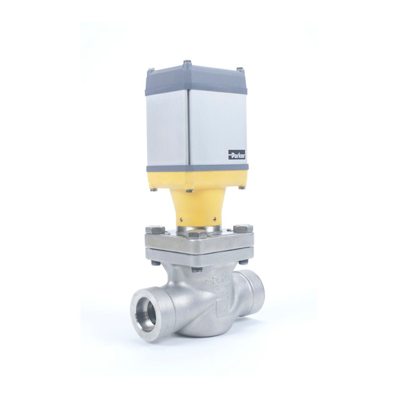
Parker Electronic Valve (PEV)
Installation Information
Operation
Prior to installing the P-Series Electronic Valve (PEV) the included safety bulletins
must be read and understood.
Refrigerants
Suitable for ammonia, CO
, and other
2
common refrigerants
Liquid Temperature Range
-60ºC to 120ºC (-76ºF to 248ºF)
Ambient Temperature Range
-40ºC to 50ºC (-40ºF to 122ºF)
Maximum Rated Pressure (MRP)
52 barg (754 psig)
Figure 1: Components
1 - Port Plate Assembly
2 - Bolts, Port Plate
3 - Valve Body
4 - Gasket, Port Plate (New)
Figure 6: Port Plate Torque Specs
Port
Bolt Size
20 mm (
3
⁄
") to 25 mm (1")
M12 x 1.75
4
32 mm (1
1
⁄
") to 40 mm (1
1
⁄
")
M16 x 2
4
2
Installation
All personnel working on valves must be qualified to work on refrigeration
systems. If there are any questions contact Sporlan Division - Refrigeration
Business Unit before proceeding with the work.
All valves are packed for a maximum protection. Unpack carefully. Check the carton
to make sure all items are unpacked, see Figure 1 for the list of items included.
Do not remove the protective coverings from the inlet and outlet of the valve until
the valve is ready to be installed. Protect the inside of the valve from dirt and chips
before and during installation. In the event the valve is left disassembled for any
length of time, protecting the components is essential. Place the components in a
plastic bag and store them in an area where they will not be damaged.
The valve should be installed in a location where it is easily accessible for
adjustment and maintenance. The location should be such that the body cannot be
easily damaged by material handing equipment. Proper indicating gauges should
be installed to be easily visible to the operating engineer for system checks and
adjustment purposes.
The valve should be disassembled before welding to prevent damage to o-rings
and teflon (PTFE) components. First remove the port plate by unbolting the bolts as
shown in Figure 2. If the port plate does not come apart easily, rotate the port plate
45º and use the corners to pry the port plate out. If using a tool, such as a screw
driver, it is important to be careful not to damage any gasket surfaces.
The current port plate gasket must be removed, as shown in Figure 3, and
discarded. A replacement gasket is provided with every purchase of a new valve.
The PEV valves must be mounted in the upright horizontal position with the actuator
on the top.
The valve must be installed with the arrow pointing in the direction of
flow for the valve to function properly.
Installers need to follow a WPS (Welding Procedure Specification) for all welding.
The procedure and welder doing the weld must be qualified to perform that
procedure.
The codes applicable to the welding of socket weld valves require that the pipe
be inserted into the socket until bottomed against the stop, then backed out
approximately
1
⁄
of an inch (1.6 mm) before welding. Use of welding rings is
16
optional but recommended for butt weld valves. They help alignment, control gap
for full penetration welding, and reduce welding debris entry.
Parker Hannifin Corporation
Sporlan Division - Refrigeration Business Unit
2445 South 25th Avenue
Broadview, IL 60155-3891 USA
Phone: (708) 681-6300
Fax: (708) 681-6306
P/N 313906RSD B
Date: 11-20
ECO: 0345229
ENGLISH
Maximum Operating Pressure
Differential (MOPD)
Port
20 mm (
3
⁄
") to
4
52 bard (754 psid)
25 mm (1")
32 mm (1
1
⁄
") to
4
28 bard (406 psid)
40 mm (1
1
⁄
")
2
Connection Types
SW, BW ANSI, and BW Metric (DN)
Figure 5: Re-Assembly
1 - Gasket, Port Plate (New)
Nm
Ft Lb
61
45
149
110
1
MOPD
2
3
4
5
ISO 9001 CERTIFIED
1
2
3
X4
Discard
X4
1
4
1
4
2
3
X4
Advertisement
Table of Contents

Related Manuals for Parker PEV


Summary of Contents for Parker PEV
- Page 1 The current port plate gasket must be removed, as shown in Figure 3, and discarded. A replacement gasket is provided with every purchase of a new valve. The PEV valves must be mounted in the upright horizontal position with the actuator on the top.
- Page 2 D. Place the gasket, 319287, onto the top of the port plate and carefully replace the PEV magnetic cap assembly. E. Torque the PEV magnetic cap assembly to 75 ft-lbs (102 N-m) by turning it in a clockwise rotation. See bulletin 24-00 for information on the PEV valve.
Need help?
Do you have a question about the PEV and is the answer not in the manual?
Questions and answers