Emerson Rosemount 648 Quick Start Manual
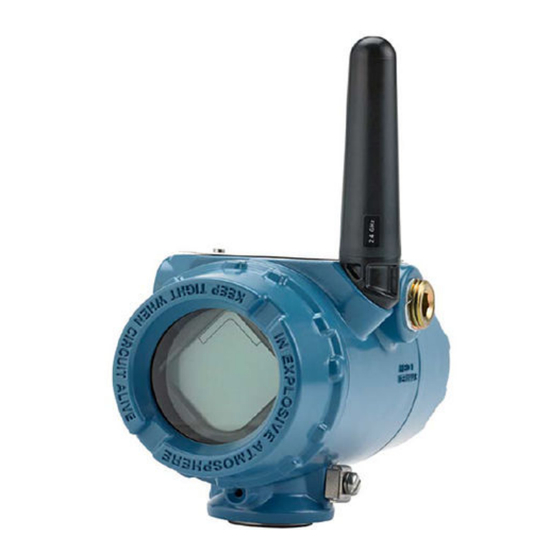
Wireless temperature transmitter with rosemount x-well technology
Hide thumbs
Also See for Rosemount 648:
- Reference manual (92 pages) ,
- Quick start manual (36 pages) ,
- Quick installation manual (18 pages)

Related Manuals for Emerson Rosemount 648


Summary of Contents for Emerson Rosemount 648
- Page 1 Quick Start Guide 00825-0200-4648, Rev EH February 2020 ™ Rosemount 648 Wireless Temperature Transmitter ™ with Rosemount X-well Technology...
-
Page 2: Table Of Contents
Device Install Kit/DD Revision Revision 4, DD Revision 1 or higher NOTICE This guide provides basic information for the Rosemount 648 Wireless. It does not provide instructions for detailed configuration, diagnostics, maintenance, service, troubleshooting, or installations. Refer to the Rosemount 648 Wireless Reference Manual for more instruction. -
Page 3: Wireless Considerations
Upon installation, ensure each conduit entry is either sealed with a conduit plug using approved thread sealant, or has an installed conduit fitting or cable gland with appropriate threaded sealant. Note the conduit entries on the Emerson 781 Field Link are threaded ½–14 NPT. Quick Start Guide... - Page 4 Field Communicator connections The Black Power Module needs to be installed in the device for the Field Communicator to interface with the Rosemount 648 Wireless. For HART Wireless Transmitter communication via a Field Communicator, a Rosemount 648 Wireless Device Dashboard (DD) is required. Rosemount 648 Wireless Transmitters equipped with Rosemount X-well Technology requires DD revision 648 Dev.
-
Page 5: Physical Installation
February 2020 Quick Start Guide Physical installation Rosemount 648 Wireless installation The Rosemount 648 Wireless can be installed in one of two configurations: • Direct Mount, where the sensor is connected directly to the Rosemount 648 Wireless housing’s conduit entry. - Page 6 3 ft. (1 m) from any large structures or buildings, to allow clear communication to other devices. Figure 2-2: Possible Antenna Rotation - Direct Mount Remote mount Procedure 1. Install sensor according to standard installation practices using an approved thread sealant on all connections. Rosemount 648...
- Page 7 February 2020 Quick Start Guide 2. Run wiring (and conduit, if necessary) from the sensor to the Rosemount 648 Wireless. 3. Pull wiring through the threaded conduit entry of the Rosemount 648 Wireless. 4. Attach sensor wiring to the terminals as indicated on the wiring diagram.
- Page 8 Figure 2-4: Possible Antenna Rotation - Remote Mount Rosemount X-well Installation Rosemount X-well Technology is only available in the Rosemount 648 Wireless and 0085 pipe clamp sensor factory assembled complete point solution. Rosemount X-well Technology will only work as specified with factory supplied and assembled pipe clamp sensor.
- Page 9 February 2020 Quick Start Guide Figure 2-5: Rosemount 648 Wireless with Rosemount X-well Technology Installation Drawing Quick Start Guide...
-
Page 10: Verify Operation
Gateway’s integrated web server, or using AMS Wireless Suite or AMS Device Manager. LCD display During normal operation, the LCD display will show the PV value at the confirmed update rate. Refer to the Rosemount 648 Wireless Reference Manual for error codes and other LCD display messages. Select the Diagnostic button to display the TAG, Device ID, Network ID, Network Join Status, and Device Status screens. - Page 11 Quick Start Guide Wireless Gateway If the Rosemount 648 Wireless was configured with the Network ID and Join Key and sufficient time for network polling has passed, the transmitter will be connected to the network. To verify device operation and connectivity using the Wireless Gateway's web based user interface, navigate to the Devices page.
- Page 12 ID and join key may be changed in the wireless device by using the following Fast Key sequence. Table 3-2: Wireless Configuration Fast Key Sequence Function Fast Key Menu items sequence Wireless Configuration 2, 2, 1 Network ID, Join to Network, Broadcast Info Rosemount 648...
-
Page 13: Reference Information
February 2020 Quick Start Guide Reference information The Rosemount 648 Wireless is compatible with a number of RTD and thermocouple sensor types. Figure 4-1 shows the correct input connections to the sensor terminals on the transmitter. Figure 4-2, Figure 4-3, and Figure show the lead wire configurations for Rosemount sensors. - Page 14 + Black (2) + Pink (2) + Green (2) – White (3) – White (3) – White (3) Note The wiring diagrams shown above apply only to Rosemount sensors. Table 4-1 lists the Fast Key sequences for common transmitter functions. Rosemount 648...
- Page 15 February 2020 Quick Start Guide Table 4-1: Rosemount 648 Wireless Fast Key Sequence Function Fast Key Menu items sequence Device Information 2, 2, 7 Tag, Long Tag, Descriptor, Message, Date Guided Setup 2, 1 Configure Sensor, Join to Network, Config Advance Broadcasting,...
-
Page 16: Power Module Replacement
Consult the materials safety data sheet for battery specific information. Reference conditions are 70 °F (21° C), transmit rate of once per minute, and routing data for three additional network devices. Rosemount 648... - Page 17 February 2020 Quick Start Guide Shipping considerations The unit was shipped to you without the Black Power Module installed. Remove the module prior to shipping the unit. Quick Start Guide...
-
Page 18: Product Certifications
RF spectrum. Nearly every country requires this type of product certification. Emerson is working with governmental agencies around the world to supply fully compliant products and remove the risk of violating country directives or laws governing wireless device usage. - Page 19 2. The surface resistivity of the antenna is greater than 1 GΩ . To avoid electrostatic charge build-up, it must not be rubbed or cleaned with solvents or dry cloth. 3. The Rosemount 648 Wireless Transmitter shall only be used with the ™ 701PBKKF Rosemount SmartPower...
- Page 20 II 1 G Ex ia IIC T4 Ga, T4(-60 °C ≤ T ≤ +70 °C) II 1 G Ex ia IIC T5 Ga, T5(-60 °C ≤ T ≤ +40 °C) For use with Rosemount SmartPower power module part number 753-9220-0001, or for use with Emerson SmartPower option 701PBKKF. Rosemount 648...
- Page 21 February 2020 Quick Start Guide Sensor terminal parameters = 6.6 V = 26.2 mA = 42.6 mW = 11 μF = 25 mH Special Conditions for Safe Use (X): 1. The surface resistivity of the antenna is greater than 1 GΩ. To avoid electrostatic charge build-up, it must not be rubbed or cleaned with solvents or dry cloth.
- Page 22 3. The Rosemount 648 enclosure may be made of aluminum alloy and given a protective polyurethane paint finish; however, care should be taken to protect it from impact or abrasion if located in a Zone 0 area.
- Page 23 February 2020 Quick Start Guide Markings Ex ia IIC T4 (–60 °C ≤ T ≤+70 °C), Ex ia IIC T5 (–60 °C ≤ T ≤ +40 °C); IP66 Sensor terminal parameters = 6.6 V = 26.2 mA = 42.6 mW = 11 μF = 25 mH Special Condition for Safe Use (X):...
- Page 24 ≤ +70 °C) T5 (–60 °C ≤ T ≤ +40 °C) Sensor terminal parameters = 6.6 V = 26.2 mA = 42.6 mW = 11 μF = 25 mH Special Condition for Safe Use (X): 1. See certificate for special conditions. Rosemount 648...
- Page 25 February 2020 Quick Start Guide 6.14 Republic of Korea 6.14.1 IP Republic of Korea Intrinsic Safety Certificate 11-KB4BO-0071 Markings Ex ia IIC T4/T5 T4 (–60 °C +70 °C) T5 (–60 °C +40 °C) Sensor terminal parameters = 6.6 V = 26.2 mA = 42.6 mW = 10.9 μF = 25 mH...
-
Page 26: Declaration Of Conformity
Quick Start Guide February 2020 Declaration of Conformity Rosemount 648... - Page 27 February 2020 Quick Start Guide Quick Start Guide...
-
Page 28: China Rohs
Quick Start Guide February 2020 China RoHS Rosemount 648... - Page 29 February 2020 Quick Start Guide Quick Start Guide...
- Page 30 Quick Start Guide February 2020 Rosemount 648...
- Page 31 February 2020 Quick Start Guide Quick Start Guide...
- Page 32 The Emerson logo is a Twitter.com/Rosemount_News trademark and service mark of Emerson Electric Facebook.com/Rosemount Co. Rosemount is a mark of one of the Emerson Youtube.com/user/ family of companies. All other marks are the RosemountMeasurement property of their respective owners.
Need help?
Do you have a question about the Rosemount 648 and is the answer not in the manual?
Questions and answers