Emerson Rosemount 644R Quick Start Manual
Smart temperature transmitters
Hide thumbs
Also See for Rosemount 644R:
- Reference manual (78 pages) ,
- Quick start manual (48 pages) ,
- Quick start manual (36 pages)

Related Manuals for Emerson Rosemount 644R


Summary of Contents for Emerson Rosemount 644R
- Page 1 Quick Start Guide 00825-0100-4728, Rev DA June 2016 Rosemount 644H (Device Revision 7 or ™ Previous) and 644R Smart Temperature Transmitters...
-
Page 2: Table Of Contents
June 2016 Quick Start Guide NOTICE This guide provides basic guidelines for the Rosemount 644. It does not provide instructions for detailed configuration, diagnostics, maintenance, service, troubleshooting, or installation. Refer to the Rosemount Reference Manual for more instruction. The manual and this guide are also available electronically on EmersonProcess.com/Rosemount. -
Page 3: Configure (Bench Calibration)
Quick Start Guide June 2016 1.0 Configure (bench calibration) The Rosemount 644 communicates using the Field Communicator (communication requires a loop resistance between 250 and 1100 ohms. Do not operate when power is below 12 Vdc at the transmitter terminal). Refer to the Rosemount 644 Reference Manual and the Field Communicator... -
Page 4: Verify Configuration
June 2016 Quick Start Guide 2.0 Verify configuration The traditional interface Fast Key sequences in Table 1and Device Dashboard Fast Key Sequences in Table 2 may be used for transmitter configuration and startup. 2.1 Field Communicator user interface The Traditional Interface Fast Key Sequences can be found on Table 1 on page Figure 2. - Page 5 Quick Start Guide June 2016 Table 1. Traditional Interface Fast Key Sequences Function Fast Keys Function Fast Keys Active Calibrator 1, 2, 2, 1, 3 Open Sensor Holdoff 1, 3, 5, 3 Alarm/Saturation 1, 3, 3, 2 Percent Range 1, 1, 5 AO Alarm Type 1, 3, 3, 2, 1 Poll Address...
- Page 6 June 2016 Quick Start Guide 2.2 Input/verify Callendar Van-Dusen constants If sensor matching is being used with this combination of a transmitter and sensor, verify the constants input. 1. From the Home screen, select 1 Device Setup, 3 Configuration, 2 Sensor Config, 1 Sensor 1, 3 Cal Van-Dusen.
-
Page 7: Set The Switches
– rotate in 90° increments). 6. Apply power and set the loop to automatic control. 3.2 Rosemount 644R (switch on middle of front panel) 1. Open the front door of the Rosemount 644R Rail Mount Transmitter. 2. Set the switch to the desired position. -
Page 8: Mount The Transmitter
June 2016 Quick Start Guide 4.0 Mount the transmitter Mount the transmitter at a high point in the conduit run to prevent moisture from draining into the transmitter housing. 4.1 Typical connection head installation Head mount transmitter with DIN plate style sensor 1. -
Page 9: June
Quick Start Guide June 2016 4.2 Typical universal head installation Head mount transmitter with threaded sensor 1. Attach the thermowell to the pipe or process container wall. Install and tighten thermowells before applying process pressure. 2. Attach necessary extension nipples and adapters to the thermowell. Seal the nipple and adapter threads with silicone tape. - Page 10 June 2016 Quick Start Guide 4.3 Rail mount transmitter and sensor 1. Attach the transmitter to a suitable rail or panel. 2. Attach the thermowell to the pipe or process container wall. Install and tighten the thermowell, according to plant standards, before applying pressure.
- Page 11 Quick Start Guide June 2016 4.4 Rail mount transmitter with threaded sensor 1. Attach the transmitter to a suitable rail or panel. 2. Attach the thermowell to the pipe or process container wall. Install and tighten the thermowell before applying pressure. 3.
-
Page 12: Wire And Apply Power
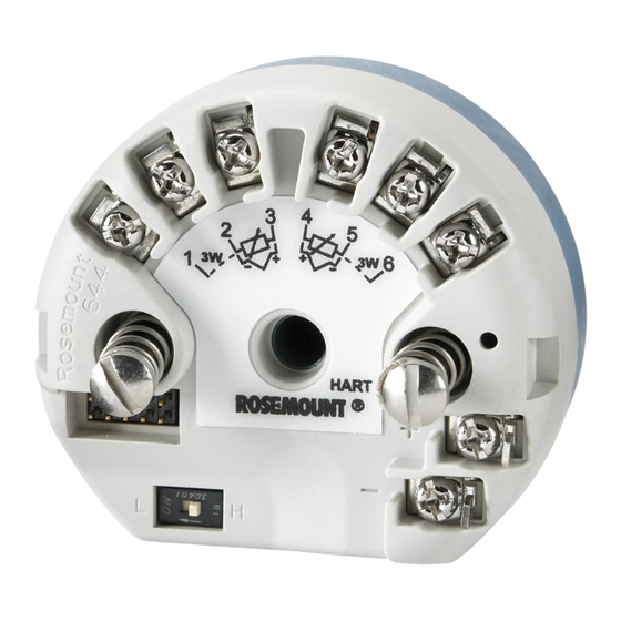
4. Tighten the terminal screws. When tightening the sensor and power wires, the max torque is 6 in-lbs (0.7 N-m). 5. Reattach and tighten the cover (if applicable). 6. Apply power (12–42 Vdc). Rosemount 644H Rosemount 644R Max torque is 6 in-lb. (0/7 N-m) A. Sensor terminals B. Communication terminals C. -
Page 13: Ground The Transmitter
Quick Start Guide June 2016 5.4 Ground the transmitter Ungrounded thermocouple, mV, and RTD/Ohm inputs Each process installation has different requirements for grounding. Use the grounding options recommended by the facility for the specific sensor type, or begin with grounding option 1 (the most common). Option 1 1. - Page 14 June 2016 Quick Start Guide Option 3 1. Ground sensor wiring shield at the sensor, if possible. 2. Ensure the sensor wiring and signal wiring shields are electrically isolated from the transmitter housing. 3. Do not connect the signal wiring shield to the sensor wiring shield. 4.
-
Page 15: Perform A Loop Test
Quick Start Guide June 2016 6.0 Perform a loop test The loop test command verifies transmitter output, loop integrity, and operation of any recorders or similar devices installed in the loop. 6.1 Traditional interface 1. Connect an external ampere meter in series with the transmitter loop (so the power to the transmitter goes through the meter at some point in the loop.) 2. -
Page 16: Product Certifications
June 2016 Quick Start Guide 7.0 Product Certifications Rev 1.9 7.1 European Directive Information A copy of the EC Declaration of Conformity can be found at the end of the Quick Start Guide. The most recent revision of the EC Declaration of Conformity can be found at EmersonProcess.com/Rosemount. -
Page 17: Process Temperature
Quick Start Guide June 2016 Special Conditions for Safe Use (X): 1. When no enclosure option is selected, the Rosemount 644 Transmitter shall be installed in a final enclosure meeting type of protection IP20 and meeting the requirements of ANSI/ISA 61010-1 and ANSI/ISA 60079-0. 2. - Page 18 June 2016 Quick Start Guide Special Conditions for Safe Use (X): 1. The equipment must be installed in an enclosure which affords it a degree of protection of at least IP20 in accordance with the requirements of IEC 60529. Non-metallic enclosures must have a surface resistance of less than 1 GΩ;...
- Page 19 Quick Start Guide June 2016 Special Conditions of Certification (X): 1. See certificate for ambient temperature range. 2. The non-metallic label may store an electrostatic charge and become a source of ignition in Group III environments. 3. Guard the LCD display cover against impact energies greater than 4 joules. 4.
- Page 20 June 2016 Quick Start Guide Special Conditions of Certification (X): 1. See certificate for ambient temperature range. 2. The non-metallic label may store an electrostatic charge and become a source of ignition in Group III environments. 3. Guard the LCD display cover against impact energies greater than 4 joules. 4.
- Page 21 Quick Start Guide June 2016 Special Conditions for Safe Use (X): 1. Temperature Assembly using temperature sensor type Rosemount 65, 68, 75, 183, 185 are certified. 2. The ambient temperature range is: Gas/dust T code Ambient temperature –40 °C ≤ T ≤...
- Page 22 June 2016 Quick Start Guide Special Conditions for Safe Use (X): 1. The ambient temperature range is: For Rosemount 644 Fieldbus, PROFIBUS, and Legacy 644 HART Transmitter output Max input power: (W) T code Ambient temperature -60 °C ≤ T ≤...
- Page 23 Quick Start Guide June 2016 For Enhanced Rosemount 644 HART: Terminals of power supply (+, –) Max internal Max input Max input Max input parameters: voltage: current: power: (mA) (nF) (mH) ≤ +80 °C) 150 (T ≤ +70 °C) 170 (T 0.67/0.8 ≤...
- Page 24 June 2016 Quick Start Guide N3 China Type n Certificate: GYJ15.1502 Standards: GB3836.1-2000, GB3836.8-2003 Markings: Ex nA nL IIC T5/T6 Gc Special Conditions for Safe Use (X): 1. The relation among T code, ambient temperature range is as following: For Rosemount 644 Fieldbus, PROFIBUS, and Legacy 644 HART: T code Ambient temperature -40 °C ≤...
- Page 25 Quick Start Guide June 2016 Japan E4 Japan Flameproof Certificate: TC20671 [J2 with LCD], TC20672 [J2], TC20673 [J6 with LCD], TC20674 [J6] Markings: Ex d IIC T5 Combinations K1 Combination of E1, I1, N1, and ND K2 Combination of E2 and I2 K5 Combination of E5 and I5 K7 Combination of E7, I7, and N7 KA Combination of K6, E1, and I1...
- Page 26 June 2016 Quick Start Guide 7.4 Specification tables Table 3. Process Temperature T130 Max Ambient +40 °C +60 °C +60 °C +60 °C +60 °C +60 °C +70 °C Transmitter with LCD display 0-in. 55 °C 70 °C 95 °C 95 °C 95 °C 95 °C...
- Page 27 Quick Start Guide June 2016 Figure 5. Rosemount 644 Declaration of Conformity...
- Page 28 June 2016 Quick Start Guide...
- Page 29 Quick Start Guide June 2016...
- Page 30 June 2016 Quick Start Guide...
- Page 31 Quick Start Guide June 2016 China RoHS Rosemount 644 List of Rosemount 644 Parts with China RoHS Concentration above MCVs Hazardous Substances Hexavalent Polybrominated Polybrominated Part Name Lead Mercury Cadmium Chromium biphenyls diphenyl ethers (Pb) (Hg) (Cd) (Cr +6) (PBB) (PBDE) Electronics Assembly...
- Page 32 +65 6777 8211 Standard Terms and Conditions of Sale can be found at www.Emerson.com/en-us/pages/Terms-of-Use.aspx +65 6777 0947 The Emerson logo is a trademark and service mark of Emerson Enquiries@AP.EmersonProcess.com Electric Co. AMS, Rosemount, and Rosemount logotype are trademarks of Middle East and Africa Regional Office Emerson Process Management.
Need help?
Do you have a question about the Rosemount 644R and is the answer not in the manual?
Questions and answers