
Related Manuals for Emerson Rosemount 644 with HART Protocol


Summary of Contents for Emerson Rosemount 644 with HART Protocol
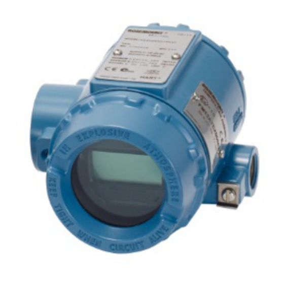
- Page 1 Reference Manual 00809-0200-4728, Rev SA July 2018 ™ Rosemount 644 Temperature Transmitter ® with HART Protocol...
-
Page 3: Table Of Contents
Reference Manual Contents 00809-0200-4728, Rev SA July 2018 Contents 1Section 1: Introduction Using this manual..............1 1.1.1 Transmitter overview. - Page 4 Contents Reference Manual 00809-0200-4728, Rev SA July 2018 2.9.1 Tag, date, descriptor and message ......... . 27 2.10 Configure measurement filtering .
- Page 5 Reference Manual Contents 00809-0200-4728, Rev SA July 2018 4Section 4: Electrical Installation Overview ..............55 Safety messages.
- Page 6 Contents Reference Manual 00809-0200-4728, Rev SA July 2018 Return of materials ............. 80 7Section 7: Safety Instrumented Systems (SIS) Certification SIS certification.
- Page 7 Using non-nuclear qualified products in applications that require nuclear-qualified hardware or products may cause inaccurate readings. ™ For information on Rosemount nuclear-qualified products, contact a Emerson Sales Representative. Failure to follow these installation guidelines could result in death or serious injury.
- Page 8 Reference Manual Title Page 00809-0200-4728, Rev SA July 2018 Title Page...
-
Page 9: Using This Manual
Introduction Reference Manual July 2018 00809-0200-4728 Rev SA Section 1 Introduction Using this manual ™ This manual is designed to assist in the installation, operation, and maintenance of Rosemount ® Head Mount, Field Mount, and Rail Mount Transmitters with the HART protocol. -
Page 10: Transmitter Overview
Completely encapsulated electronics to ensure long term transmitter reliability Refer to the following literature for a full range of compatible connection heads, sensors, and thermowells provided by Emerson. Rosemount Volume 1 Temperature Sensors and Accessories (English) Product Data Sheet ... -
Page 11: Overview
Reference Manual Configuration 00809-0200-4728, Rev SA July 2018 Section 2 Configuration Overview ................page 3 Safety messages . -
Page 12: Safety Messages
For instructions on how to change the HART revision of your transmitter, see “System readiness” on page 2.3.1 Confirm correct device driver Verify the latest Device Driver files are loaded on your systems to ensure proper communications. Download the latest Device Driver at Emerson.com/Rosemount or Fieldcomm.org. Configuration... -
Page 13: Confirm Correct Device Driver
Reference Manual Configuration 00809-0200-4728, Rev SA July 2018 Table 2-1. Rosemount 644 Device Revisions and Files Review Software date Identify device Find device driver files Review instructions functionality HART Universal Device Changes to NAMUR Software HART Software Date Document Revision Revision Revision Revision... -
Page 14: Selecting A Configuration Tool
4, it is critical that the latest DD’s are loaded into the Field Communicator for optimal transmitter performance. Visit Emerson.com/Rosemount to download latest DD library. Turn on the Field Communicator by pressing the ON/OFF key. The Field Communicator will search for a HART-compatible device and indicate when the connection is made. - Page 15 Full configuration capability with AMS Device Manager requires loading the most current Device Descriptor (DD) for this device. Download the latest DD at Emerson.com/Rosemount or Fieldcomm.org. Note All steps listed in this product manual using AMS Device Manager assume the use of Version 11.5.
-
Page 16: Setting The Loop To Manual
Configuration Reference Manual 00809-0200-4728, Rev SA July 2018 Figure 2-3. LOI Configuration Buttons A. Configuration buttons Table 2-2. LOI Button Operation Button Left SCROLL Right ENTER LOI password An LOI password can be entered and enabled to prevent review and modification of device configuration via the LOI. -
Page 17: Hart Software Lock
Reference Manual Configuration 00809-0200-4728, Rev SA July 2018 2.4.5 HART software lock The HART Software Lock prevents changes to the transmitter configuration from all sources; all changes requested via HART by the Field Communicator, AMS Device manager or the LOI will be rejected. The HART Lock can only be set via HART communication, and is only available in HART Revision 7 mode. -
Page 18: Ams Device Manager
Configuration Reference Manual 00809-0200-4728, Rev SA July 2018 2.5.2 AMS Device Manager 1. Right click on the device and select Configuration Properties from the menu. 2. Navigate the tabs to review the transmitter configuration data. 2.5.3 Press any configuration button to activate the LOI. Select VIEW CONFIG to review the below parameters. Use the configuration buttons to navigate through the menu. -
Page 19: Basic Configuration Of The Transmitter
Reference Manual Configuration 00809-0200-4728, Rev SA July 2018 VIEW CONFIG ON/OFF SENSOR 1 ZERO TRIM SENSOR 2* UNITS ANALOG RERANGE LOOP TEST DISPLAY DISPLAY GOOD EXTENDED MENU DIFF EXIT MENU % RANGE TERM MNMAX1* MNMAX2* MNMAX3* MNMAX4* BACK TO MENU EXIT MENU Basic configuration of the transmitter The Rosemount 644 Transmitter must be configured for certain basic variables in order to be... -
Page 20: Mapping The Hart Variables
Configuration Reference Manual 00809-0200-4728, Rev SA July 2018 Follow flow chart to select the desired mapped variables. Use the SCROLL and ENTER buttons to select each variable. Save by selecting SAVE as indicated on the LCD screen when prompted. See Figure 2-4 on page 12 for an example of a mapped variable with the LOI. -
Page 21: Configuring The Sensor(S)
Contact an Emerson representative for information on the temperature sensors, thermowells, and accessory mounting hardware that is available through Emerson. 2-wire RTD offset The 2-wire offset feature allows the measured lead wire resistance to be input and corrected for, which results in the transmitter adjusting its temperature measurement for the error caused by this added resistance. -
Page 22: Setting Output Units
Configuration Reference Manual 00809-0200-4728, Rev SA July 2018 2.6.3 Setting output units The Units can be configured for a number of different parameters in the Rosemount 644 Transmitter. Individual Units can be configured for: Sensor 1 Sensor 2 Terminal temperature ... -
Page 23: Configure Dual Sensor Options
Reference Manual Configuration 00809-0200-4728, Rev SA July 2018 Note The list of choices available for Units after the primary menu is dependent on your Sensor configuration settings. Configure dual sensor options Dual-sensor configuration deals with the functions that can be used with a transmitter ordered with Dual Sensor inputs. -
Page 24: Differential Temperature Configuration
Configuration Reference Manual 00809-0200-4728, Rev SA July 2018 To configure the Differential Temperature on the LOI, the Units and Damping values must be set separately. Reference figures below for where to find these in the menu. Figure 2-7. Configuring Differential Units with LOI DEG C UNITS VIEW CONFIG CHANGE ALL... -
Page 25: Average Temperature Configuration
Reference Manual Configuration 00809-0200-4728, Rev SA July 2018 AMS Device Manager 1. Right click on the device and select Configure. 2. In the left navigation pane select Manual Setup. 3. On the Calculated Output Tab find the Average Temperature group box. 4. -
Page 26: Hot Backup Configuration
Configuration Reference Manual 00809-0200-4728, Rev SA July 2018 Note If Sensor 1 and/or Sensor 2 should fail while PV is configured for average temperature and Hot Backup is not enabled, the transmitter will go into alarm. For this reason, it is recommended when PV is Sensor Average, that Hot Backup be enabled when dual-element sensors are used, or when two temperature measurements are taken from the same point in the process. - Page 27 Reference Manual Configuration 00809-0200-4728, Rev SA July 2018 To configure Hot Backup on the LOI, enable the mode and set the PV values. Reference Figure 2-11 where to find these in the menu. Figure 2-11. Configuring Hot Backup with LOI HOT BACK MODE CALIBRAT HOT BACK PV...
-
Page 28: Sensor Drift Alert Configuration
Configuration Reference Manual 00809-0200-4728, Rev SA July 2018 Field Communicator The Field Communicator will walk you through a method to correctly configure the necessary elements of a sensor drift alert feature. From the HOME screen, enter the Fast Key sequence. 2, 1, 6 Device Dashboard Fast Keys AMS Device Manager... -
Page 29: Configure Device Outputs
Reference Manual Configuration 00809-0200-4728, Rev SA July 2018 Configure device outputs 2.8.1 Re-range the transmitter Re-ranging the transmitter sets the measurement range to the limits of the expected readings for a certain application. Setting the measurement range to the limits of expected readings maximizes transmitter performance;... -
Page 30: Damping
Configuration Reference Manual 00809-0200-4728, Rev SA July 2018 2.8.2 Damping The damping function changes the response time of the transmitter to smooth variations in output readings caused by rapid changes in input. Determine the appropriate damping setting based on the necessary response time, signal stability, and other requirements of the loop dynamics of the system. - Page 31 Reference Manual Configuration 00809-0200-4728, Rev SA July 2018 Damping can be applied to a number of parameters in the Rosemount 644 Transmitter. Variables that can be damped are: Primary Variable (PV) Sensor 1 Sensor 2 Differential temperature ...
-
Page 32: Configure Alarm And Saturation Levels
Configuration Reference Manual 00809-0200-4728, Rev SA July 2018 2.8.3 Configure alarm and saturation levels In normal operation, the transmitter will drive the output in response to measurements between the lower to upper saturation points. If the temperature goes outside the sensor limits, or if the output would be beyond the saturation points, the output will be limited to the associated saturation point. -
Page 33: Configuring The Lcd Display
Reference Manual Configuration 00809-0200-4728, Rev SA July 2018 Field Communicator From the HOME screen, enter the Fast Key sequence. 2, 2, 5, 6 Device Dashboard Fast Keys AMS Device Manager 1. Right click on the device and select Configure. 2. In the left navigation pane select Manual Setup. 3. - Page 34 Configuration Reference Manual 00809-0200-4728, Rev SA July 2018 Figure 2-16. LOI and LCD Display LCD display Field Communicator From the HOME screen, enter the Fast Key sequence. 2, 1, 4 Device Dashboard Fast Keys AMS Device Manager 1. Right click on the device and select Configure. 2.
-
Page 35: Inputting Device Information
Reference Manual Configuration 00809-0200-4728, Rev SA July 2018 Figure 2-17. Configuring the LCD Display using LOI SENSOR 1 SENSOR 2* VIEW CONFIG ANALOG SENSOR CONFIG UNITS AVG* RERANGE GOOD* LOOP TEST DIFF* DISPLAY DISPLAY % RANGE EXTENDED MENU TERM EXIT MENU MNMAX1* MNMAX2* MNMAX3*... -
Page 36: Configure Measurement Filtering
Configuration Reference Manual 00809-0200-4728, Rev SA July 2018 Field Communicator From the HOME screen, enter the Fast Key sequence. 1, 8 Device Dashboard Fast Keys AMS Device Manager 1. Right click on the device and select Configure. 2. In the left navigation pane select Manual Setup. 3. -
Page 37: Resetting The Device
Reference Manual Configuration 00809-0200-4728, Rev SA July 2018 AMS Device Manager 1. Right click on the device and select Configure. 2. In the left navigation pane select Manual Setup. 3. On the Device Tab there will be a group box called Noise Rejection, in the box AC Power Filter select from the drop down menu. -
Page 38: Open Sensor Hold Off
Configuration Reference Manual 00809-0200-4728, Rev SA July 2018 Field Communicator The following steps indicate how to turn the intermittent sensor detect (or transient filter) feature ON or OFF. When the transmitter is connected to a Field Communicator, use the Fast Key sequence and choose ON (normal setting) or OFF. -
Page 39: Diagnostics And Service
Reference Manual Configuration 00809-0200-4728, Rev SA July 2018 2.11 Diagnostics and service 2.11.1 Performing a loop test The analog loop test verifies the output of the transmitter, the integrity of the loop, and the operations of any recorders or similar devices installed in the loop. To initiate a loop test, follow the steps below. The host system may provide a current measurement for the 4–20 mA HART output. -
Page 40: Thermocouple Degradation Diagnostic
Configuration Reference Manual 00809-0200-4728, Rev SA July 2018 AMS Device Manager 1. Right click on the device and select Service Tools. 2. In the left navigation window select Simulate. 3. In the group box labeled Device Variables select the variable to simulate. a. - Page 41 Reference Manual Configuration 00809-0200-4728, Rev SA July 2018 Field Communicator From the HOME screen, enter the Fast Key sequence. 2, 2, 4, 3, 4 Device Dashboard Fast Keys AMS Device Manager 1. Right click on the device and select Configure. 2.
-
Page 42: Minimum/Maximum Tracking Diagnostic
Configuration Reference Manual 00809-0200-4728, Rev SA July 2018 2.11.4 Minimum/maximum tracking diagnostic Minimum and maximum temperature tracking (min/max tracking) when enabled records minimum and maximum temperatures with date and time stamps on Rosemount 644 HART Head Mount and Field Mount Temperature Transmitters. This feature records values for Sensor 1, Sensor 2, Differential, Average, First Good and Terminal temperatures. -
Page 43: Establishing Multi Drop Communication
Reference Manual Configuration 00809-0200-4728, Rev SA July 2018 2.12 Establishing multi drop communication Multi dropping refers to the connection of several transmitters to a single communications transmission line. Communication between the host and the transmitters takes place digitally with the analog output of the transmitters deactivated. -
Page 44: Using The Transmitter With The Hart Tri-Loop
Configuration Reference Manual 00809-0200-4728, Rev SA July 2018 Field Communicator From the HOME screen, enter the Fast Key sequence. 1, 2, 1 Device Dashboard Fast Keys AMS Device Manager 1. Right click on the device and select Configuration Properties from the menu. 2. -
Page 45: Set Process Variable Output Order
Reference Manual Configuration 00809-0200-4728, Rev SA July 2018 AMS Device Manager 1. Right click on the device and select Configure. 2. In the left navigation window select Manual Setup. 3. On the HART tab find the Burst Mode Configuration group box and fill in the necessary content. 4. -
Page 46: Transmitter Security
Configuration Reference Manual 00809-0200-4728, Rev SA July 2018 1. Configure the dual-sensor Rosemount 644 Transmitter variable map as shown: Variable Mapping Sensor 1 or sensor average Sensor 2 Differential temperature As desired 2. Configure Channel 1 of the HART Tri-Loop as TV (differential temperature). If either sensor should fail, the differential temperature output will be +9999 or –9999 (high or low saturation), depending on the position of the Failure Mode Switch (see “Set the alarm switch”... - Page 47 Reference Manual Configuration 00809-0200-4728, Rev SA July 2018 Field Communicator From the HOME screen, enter the Fast Key sequence. 2, 2, 9, 1 Write Protect 2, 2, 9, 2 HART Lock 2, 2, 9, 3 LOI Password AMS Device Manager Right click on the device and select the Configure menu.
- Page 48 Configuration Reference Manual 00809-0200-4728, Rev SA July 2018 Configuration...
-
Page 49: Overview
Reference Manual Installation 00809-0200-4728, Rev SA July 2018 Section 3 Hardware Installation Overview ................page 41 Safety messages . -
Page 50: Safety Messages
Installation Reference Manual 00809-0200-4728, Rev SA July 2018 Safety messages Instructions and procedures in this section may require special precautions to ensure the safety of the personnel performing the operations. Information that potentially raises safety issues is indicated by a warning symbol ( ). -
Page 51: Mechanical
Reference Manual Installation 00809-0200-4728, Rev SA July 2018 3.3.4 Mechanical Location When choosing an installation location and position, take into account the need for access to the transmitter. Special mounting Special mounting hardware is available for mounting a Rosemount 644 Head Mount Transmitter to a DIN rail or assembling a new Rosemount 644 Head Mount to an existing threaded sensor connection head (former option code L1). -
Page 52: Installation Procedures
Installation Reference Manual 00809-0200-4728, Rev SA July 2018 Example The maximum permissible housing temperature rise (T) can be calculated by subtracting the maximum ambient temperature (A) from the transmitter’s ambient temperature specification limit (S). For instance, if A = 40 °C. T = S - A T = 85 °C –... -
Page 53: Set The Alarm Switch
Reference Manual Installation 00809-0200-4728, Rev SA July 2018 3.4.1 Set the alarm switch Make certain that the alarm switch is set to the desired position before putting the device into operation to ensure correct function in the instance of a failure. Without an LCD display 1. -
Page 54: Mount The Transmitter
Installation Reference Manual 00809-0200-4728, Rev SA July 2018 3.4.2 Mount the transmitter Mount the transmitter at a high point in the conduit run to prevent moisture from draining into the transmitter housing. The Rosemount 644 Head Mount installs: In a connection head or universal head mounted directly on a sensor assembly. ... -
Page 55: Install The Device
Reference Manual Installation 00809-0200-4728, Rev SA July 2018 3.4.3 Install the device Head mount transmitter with DIN plate style sensor installation 1. Attach the thermowell to the pipe or process container wall. Install and tighten the thermowell before applying process pressure. 2. - Page 56 Installation Reference Manual 00809-0200-4728, Rev SA July 2018 5. To verify the correct installation of Integral Transient Protection (option code T1) on the Rosemount 644 device, confirm the following steps have been completed: a. Ensure the transient protector unit is firmly connected to the transmitter puck assembly. b.
- Page 57 Reference Manual Installation 00809-0200-4728, Rev SA July 2018 Field mount transmitter with threaded sensor installation 1. Attach the thermowell to the pipe or process container wall. Install and tighten thermowells before applying process pressure. 2. Attach necessary extension nipples and adapters to the thermowell. 3.
- Page 58 Installation Reference Manual 00809-0200-4728, Rev SA July 2018 Rail mount transmitter and sensor 1. Attach the transmitter to a suitable rail or panel. 2. Attach the thermowell to the pipe or process container wall. Install and tighten the thermowell, according to plant standards, before applying pressure. 3.
-
Page 59: Multichannel Installations
Reference Manual Installation 00809-0200-4728, Rev SA July 2018 Rail mount transmitter with threaded sensor 1. Attach the transmitter to a suitable rail or panel. 2. Attach the thermowell to the pipe or process container wall. Install and tighten the thermowell before applying pressure. -
Page 60: Lcd Display Installation
Installation Reference Manual 00809-0200-4728, Rev SA July 2018 Figure 3-6. Multichannel Installations Between 250 Ω and 1100 Ω if no load resistor. A. Transmitter no. 1 B. Transmitter no.2 C. R Lead D. Readout or controller no. 1 E. Readout or controller no. 2 F. - Page 61 Reference Manual Installation 00809-0200-4728, Rev SA July 2018 Use the following procedure to install the meter. 1. If the transmitter is installed in a loop, secure the loop and disconnect the power. If the transmitter is installed in an enclosure, remove the cover from the enclosure. 2.
-
Page 62: Rev Sa July
Installation Reference Manual 00809-0200-4728, Rev SA July 2018 Installation... -
Page 63: Overview
Operation and Maintenance Reference Manual July 2018 00809-0200-4728, Rev SA Section 4 Electrical Installation Overview ................page 55 Safety messages . -
Page 64: Sensor Connections
Operation and Maintenance Reference Manual 00809-0200-4728, Rev SA July 2018 Note Do not apply high voltage (e.g., ac line voltage) to the transmitter terminals. Abnormally high voltage can damage the unit. (Sensor and transmitter power terminals are rated to 42.4 Vdc. A constant 42.4 volts across the sensor terminals may damage the unit.) ®... - Page 65 July 2018 Figure 4-2. Sensor Wiring Diagrams ™ *Emerson provides a 4-wire sensors for all single element RTDs. You can use these RTDs in 3-wire configurations by leaving the unneeded leads disconnected and insulated with electrical tape. - HART Head Mount...
-
Page 66: Power The Transmitter
Operation and Maintenance Reference Manual 00809-0200-4728, Rev SA July 2018 RTD or Ohm inputs The transmitters will accept a variety of RTD configurations, including 2-, 3- or 4-wire. If the transmitter is mounted remotely from a 3- or 4-wire RTD, it will operate within specifications, without recalibration, for lead wire resistances of up to 60 ohms per lead (equivalent to 6,000 feet of 20 AWG wire). -
Page 67: Ground The Transmitter
Reference Manual Operation and Maintenance 00809-0200-4728, Rev SA July 2018 Figure 4-3. Powering the Transmitter for Bench Configuration Rosemount 644 Head Mount and Field Mount Rosemount 644 Rail Mount ≤ R ≤ 1100 A. Power supply B. Field Communicator Note Signal loop may be grounded at any point or left ungrounded. - Page 68 If the technique does not eliminate the transmitter alarms, try another technique. If all of the techniques do not eliminate or prevent the transmitter alarms because of high EMI, contact an Emerson representative.
- Page 69 Reference Manual Operation and Maintenance 00809-0200-4728, Rev SA July 2018 4. Ensure the sensor shield is electrically isolated from the surrounding grounded fixtures. A. Sensor wires B. Transmitter C. Shield ground point 5. Connect shields together, electrically isolated from the transmitter. Option 3 1.
-
Page 70: Wiring With A Rosemount 333 Hart Tri-Loop (Hart/4-20 Ma Only)
Operation and Maintenance Reference Manual 00809-0200-4728, Rev SA July 2018 Grounded thermocouple inputs Option 1 1. Ground sensor wiring shield at the sensor. 2. Ensure the sensor wiring and signal wiring shields are electrically isolated from the transmitter housing. 3. Do not connect the signal wiring shield to the sensor wiring shield. 4. - Page 71 Reference Manual Operation and Maintenance 00809-0200-4728, Rev SA July 2018 The power supplied to the transmitter is determined by the total loop resistance and should not drop below the lift-off voltage. The lift-off voltage is the minimum supply voltage required for any given total loop resistance.
- Page 72 Operation and Maintenance Reference Manual 00809-0200-4728, Rev SA July 2018 Operation and Maintenance...
-
Page 73: Overview
Troubleshooting Reference Manual July 2018 00809-0200-4728, Rev SA Section 5 Operation and Maintenance Overview ................page 65 Safety messages . -
Page 74: Calibration Overview
Reference Manual Troubleshooting 00809-0200-4728, Rev SA July 2018 Calibration overview Calibrating the transmitter increases the measurement precision by allowing corrections to be made to the factory-stored characterization curve by digitally altering the transmitter’s interpretation of the sensor input. To understand calibration, it is necessary to understand that smart transmitters operate differently from analog transmitters. -
Page 75: Application: Linear Offset (Single-Point Trim Solution)
Reference Manual Troubleshooting 00809-0200-4728, Rev SA July 2018 Figure 5-1. Trim Single-point trim Two-point trim Temperature Temperature Transmitter System Curve Site-Standard Curve 5.4.1 Application: Linear offset (single-point trim solution) 1. Connect sensor to transmitter. Place sensor in bath between range points. 2. -
Page 76: Recall Factory Trim-Sensor Trim
Troubleshooting Reference Manual 00809-0200-4728, Rev SA July 2018 AMS Device Manager 1. Right click on the device and select Overview. 2. On the main Overview tab, select the Calibrate Sensor(s) button near the bottom of the window. 3. Follow the screen prompts through the Sensor Trimming process. Reference the below image for guidance on where to find Sensor Calibration in the LOI menu. -
Page 77: Active Calibrator And Emf Compensation
Reference Manual Troubleshooting 00809-0200-4728, Rev SA July 2018 Figure 5-3. Recalling the Sensor Trim with the LOI CALIBRAT CALIBRAT SENSOR 1 CALIB VIEW CONFIG DAMPING SENSOR 2 CALIB* SENSOR CONFIG VARIABLE MAP ANALOG TRIM UNITS FACTORY RECALL FACTORY RECALL RERANGE ALM SAT VALUES BACK TO MENU LOOP TEST... -
Page 78: Analog Output Trim
Troubleshooting Reference Manual 00809-0200-4728, Rev SA July 2018 Figure 5-4. Measurement Dynamics of Temperature Transmitter Transmitter electronics module Digital-to-Analog Analog-to-Digital Signal Microprocessor Signal Conversion Conversion Sensor and Ohm/mV Output and Scaled Output Trim adjust the signal here Trim adjust the signal here HART Analog Analog... -
Page 79: Performing A Scaled Output Trim
Transmitter-sensor matching Use Transmitter-Sensor Matching to enhance the temperature measurement accuracy of the system and ™ if you have a sensor with Callendar-Van Dusen constants. When ordered from Emerson , sensors with Callendar-Van Dusen constants are NIST-traceable. The Rosemount 644 accepts Callendar-Van Dusen constants from a calibrated RTD schedule and generates a special custom curve to match that specific sensor Resistance vs. - Page 80 Reference Manual Troubleshooting 00809-0200-4728, Rev SA July 2018 Table 5-1. Standard RTD vs. RTD with Matched CVD Constants with Standard Transmitter Accuracy System accuracy comparison at 150 °C using a PT 100 (α=0.00385) RTD with a span of 0 to 200 °C Standard RTD Matched RTD Rosemount 644...
-
Page 81: Switching Hart Revision
Reference Manual Troubleshooting 00809-0200-4728, Rev SA July 2018 AMS Device Manager 1. Right click on the device and select Configure. 2. In the left navigation pane choose Manual Setup and choose the Sensor 1 or Sensor 2 tab depending on the need. 3. -
Page 82: Loi
Troubleshooting Reference Manual 00809-0200-4728, Rev SA July 2018 5.7.4 Reference Figure 5-7 for where to find HART Rev in the LOI menu. Figure 5-7. Switching the HART Revision with the LOI VIEW CONFIG CALIBRAT ZERO TRIM DAMPING UNITS VARIABLE MAP RERANGE LOOP TEST ALM SAT VALUES... -
Page 83: Overview
Troubleshooting Reference Manual July 2018 00809-0200-4728, Rev SA Section 6 Troubleshooting Overview ................page 75 Safety messages . -
Page 84: 4-20 Ma/Hart Output
The communicator should report Dev v4, DD v1 (improved), or reference “Field Communicator” on page 6 for previous ™ versions. Contact Emerson Customer Central for assistance. Check for a minimum of 250 ohms resistance between the power supply and Transmitter does Field Communicator connection. -
Page 85: Diagnostic Messages
ALARM ALARM electronics failure, essential 2. If condition persists, replace the transmitter. electronics in the device have DEVICE DEVICE Contact the nearest Emerson Field Service failed. For example, the Electronics failure Center if necessary. transmitter may have ALARM ALARM experienced an electronics... -
Page 86: Warning Status
Troubleshooting Reference Manual 00809-0200-4728, Rev SA July 2018 Table 6-2. Failed – Fix Now Alert name LCD screen LOI screen Problem Recommended action 1. Verify the process temperature is within the specified sensor's range. Use the Sensor Information button to compare with the ALARM ALARM This message indicates that... - Page 87 Reference Manual Troubleshooting 00809-0200-4728, Rev SA July 2018 Alert name LCD screen LOI screen Problem Recommended action 1. Check terminal connections on the 644 terminal screws for corrosion. 2. Check the thermocouple loop for any WARN WARN The resistance of the signs of corrosion in terminal blocks, wire SNSR 1 SNSR 1...
-
Page 88: Other Lcd Display Messages
3. Perform a device reset. Return of materials To expedite the return process in North America, call the Emerson National Response Center toll-free at 800-654-7768. This center, available 24 hours a day, will assist you with any needed information or materials. -
Page 89: Sis Certification
Safety Instrumented Systems (SIS) Certification Reference Manual July 2018 00809-0200-4728, Rev SA Section 7 Safety Instrumented Systems (SIS) Certification SIS certification ...............page 81 Safety certified identification . -
Page 90: Installation
Safety Instrumented Systems (SIS) Certification Reference Manual 00809-0200-4728, Rev SA July 2018 Installation Installations are to be performed by qualified personnel. No special installation is required in addition to the standard installation practices outlined in this document. Always ensure a proper seal by installing the electronics housing cover(s) so that metal contacts metal. -
Page 91: Operation And Maintenance
The following proof tests are recommended. In the event that an error is found in the safety functionality, proof test results and corrective actions taken must be documented at Emerson.com/Rosemount/Safety. All proof test procedures must be carried out by qualified personnel. -
Page 92: Comprehensive Proof Test 2
Safety Instrumented Systems (SIS) Certification Reference Manual 00809-0200-4728, Rev SA July 2018 4. Use the HART communicator to view detailed device status to ensure no alarms or warnings are present in the transmitter. 5. Perform reasonability check on the sensor value(s) versus an independent estimate (i.e. from direct monitoring of BPCS value) to show current reading is good. -
Page 93: Inspection
Safety response time: five seconds 7.6.3 Product life 50 years - based on worst case component wear-out mechanisms — not based on wear-out of process sensors. Report any safety related product information at Emerson.com/Rosemount/Contact-Us. Safety Instrumented Systems (SIS) Certification... - Page 94 Safety Instrumented Systems (SIS) Certification Reference Manual 00809-0200-4728, Rev SA July 2018 Safety Instrumented Systems (SIS) Certification...
-
Page 95: A.1 Product Certifications
™ To view current Rosemount 644 Temperature Transmitter Product Certifications, follow these steps: 1. Go to Emerson.com/Rosemount/Rosemount-644. 2. Scroll as needed to the green menu bar and click Documents & Drawings. 3. Click Manuals & Guides. 4. Select the appropriate Quick Start Guide. - Page 96 Reference Manual Reference Data July 2018 00809-0200-4728, Rev SA Specifications and Reference Data...
-
Page 97: Field Communicator Menu Trees
Field Communicator Menu Trees and Fast Keys Reference Manual July 2018 00809-0200-4728, Rev SA Appendix B Field Communicator Menu Trees and Fast Keys Field Communicator menu trees Figure B-1. Overview Good (only if No Alerts) Active Alerts 1 No Active Alerts 1 Good (only if No Alerts) 2 Failed Failed... - Page 98 Reference Manual Field Communicator Menu Trees and Fast Keys July 2018 00809-0200-4728, Rev SA Figure B-2. Configure Home Sensor 1 Guided Setup 1 Overview 1 Sensor 1 Temp 1 Configure Sensors 2 Configure Configure 2 Sensor 1 Status* 2 Calibrate Sensors 3 Service Tools 1 Guided Setup 3 Sensor 1 Type...
- Page 99 Field Communicator Menu Trees and Fast Keys Reference Manual July 2018 00809-0200-4728, Rev SA Figure B-3. Service Tools Good (only if No Alerts) 1 No Active Alerts Failed 1 Invalid Configuration 2 Electronics Failure 3 Calibration Error 4 Sensor Drift Alert Active 5 Sensor 1 Open 6 Sensor 2 Open 7 Sensor 1 Shorted...
- Page 100 Reference Manual Field Communicator Menu Trees and Fast Keys July 2018 00809-0200-4728, Rev SA ® Figure B-4. Rosemount 644 HART Revision 7 Field Communicator Menu Tree – Overview Good (only if No Alerts) Active Alerts 1 No Active Alerts 1 Good (only if No Alerts) 2 Failed Failed 3 Advisory...
- Page 101 Field Communicator Menu Trees and Fast Keys Reference Manual July 2018 00809-0200-4728, Rev SA Figure B-5. Rosemount 644 HART Revision 7 Field Communicator Menu Tree - Configure Home Sensor 1 Guided Setup 1 Overview 1 Sensor 1 Temp 1 Configure Sensors 2 Configure Configure 2 Sensor 1 Status*...
- Page 102 Reference Manual Field Communicator Menu Trees and Fast Keys July 2018 00809-0200-4728, Rev SA Figure B-6. Service Tools Good (only if No Alerts) 1 No Active Alerts Failed 1 Invalid Configuration 2 Electronics Failure 3 Calibration Error 4 Sensor Drift Alert Active 5 Sensor 1 Open 6 Sensor 2 Open 7 Sensor 1 Shorted...
-
Page 103: Field Communicator Fast Keys
Field Communicator Menu Trees and Fast Keys Reference Manual July 2018 00809-0200-4728, Rev SA Field Communicator Fast Keys Table B-1. Device Revision 8 and 9 (HART 5 and 7) Field Communicator Device Dashboard Fast Key Sequences Function HART 5 HART 7 Alarm Values 2, 2, 5, 6 2, 2, 5, 6... - Page 104 Reference Manual Field Communicator Menu Trees and Fast Keys July 2018 00809-0200-4728, Rev SA Table B-1. Device Revision 8 and 9 (HART 5 and 7) Field Communicator Device Dashboard Fast Key Sequences Function HART 5 HART 7 Software Revision 1, 8, 2, 4 1, 8, 2, 4 2, 2, 7, 1, 1 2, 2, 7, 1, 1...
-
Page 105: Number Entry
Local Operator Interface Reference Manual July 2018 00809-0200-4728, Rev SA Appendix C Local Operator Interface (LOI) Number entry ..............page 97 Text entry . -
Page 106: Text Entry
Reference Manual Local Operator Interface July 2018 00809-0200-4728, Rev SA Table C-1. LOI Number Entry Current position Step Instruction (indicated by underline) Press the enter button to select the decimal, “.”, for the seventh digit. After pressing enter, all digits to the right of the decimal will now be 000011.0 zero. - Page 107 Local Operator Interface Reference Manual July 2018 00809-0200-4728, Rev SA Figure C-1. Menu Scrolling/Text and Digit Scrolling Menu scrolling Text and digit scrolling V I E W T A G C O N F I G S E N S O R T A G C O N F I G T A G...
-
Page 108: Timeout
Local Operator Interface Reference Manual July 2018 00809-0200-4728, Rev SA Timeout The LOI in standard operation will Time Out and return to the home screen after 15 minutes of inactivity. To re-enter into the LOI menu press either button. Saving and canceling The Save and Cancel functionality implemented at the end of a series of steps allows the user to save the change or exit the function without saving any of the changes. -
Page 109: Loi Menu Tree
Local Operator Interface Reference Manual July 2018 00809-0200-4728, Rev SA LOI menu tree VIEW CONFIG UNITS SENSOR 1 TYPE CONNECTION SENSOR 2 TYPE CONNECTION UPPER RANGE VALUE LOWER RANGE VALUE DAMPING VALUE HIGH ALARM LOW ALARM HIGH SATURATION LOW SATURATION BACK TO MENU EXIT MENU LOI MENU... -
Page 110: Loi Menu Tree - Extended Menu
Local Operator Interface Reference Manual July 2018 00809-0200-4728, Rev SA LOI menu tree – extended menu CALIBRAT SENSOR 1 CALIB SENSOR 2 CALIB ANALOG TRIM FACTORY RECALL BACK TO MENU EXIT MENU DAMPING PV DAMP SENSOR 1 DAMP SENSOR 2 DAMP DIFFRNTL DAMP AVERAGE DAMP 1ST GOOD DAMP... - Page 112 Sale page. +971 4 8118100 The Emerson logo is a trademark and service mark of Emerson Electric Co. Rosemount, and the Rosemount logotype are trademarks of Emerson. +971 4 8865465 All other marks are the property of their respective owners.
Need help?
Do you have a question about the Rosemount 644 with HART Protocol and is the answer not in the manual?
Questions and answers