
Related Manuals for Phoenix Mecano DewertOkin MC10


Summary of Contents for Phoenix Mecano DewertOkin MC10
- Page 1 MC10 Control Unit Installation Instructions (Translation of the original installation instructions)
-
Page 3: Foreword
MC10 control unit Foreword Foreword Document revision history Version Date Modification, change 06/10 First release 10/10 Technical specifications 02/11 Temperature monitoring 09/11 Mounting to the end product 03/20 Edition II 03/20 RoHS, toggle 04/20 Edition III Disclaimer and exclusion of liability DewertOkin is not responsible for damage resulting from: •... -
Page 4: Table Of Contents
Table of Contents MC10 control unit Table of Contents Foreword Document revision history Disclaimer and exclusion of liability Manufacturer's address Creation of a complete operating instruction manual for the entire end product Usage in medical products Table of Contents General Information Configurations About these installation instructions Conventions used... - Page 5 MC10 control unit Table of Contents Disposal 10.1 Packaging material 10.2 Components in the control unit EU Declaration of Conformity Additional information 66648 7.0...
-
Page 6: General Information
General Information MC10 control unit General Information Configurations The MC10 control unit is available in different versions: with and without the designation CARE or HOSP. The "Possible Combinations" Chapter describes the different device combinations that are available. About these installation instructions In order to install the MC10 control unit successfully and safely in the end product, these installation in- structions must be observed. -
Page 7: Safety Notices
MC10 control unit Safety notices Safety notices Proper and intended usage The MC10 control unit is intended for use • as a control unit and power supply for the appropriate DewertOkin drive systems. • for care purposes, • or in hospitals. CAUTION The MC10 control unit should only be used for the applications described above. -
Page 8: Selection And Qualification Of Personnel
Safety notices MC10 control unit Using the drive systems in medical applications This DewertOkin product meets the safety requirements described in IEC 60601-1. We strongly recommend that the end product (including all its components) which you are manu- facturing for a medical application should also comply with the safety requirements found in IEC 60601-1. -
Page 9: Product Labelling
MC10 control unit Safety notices Product labelling 2.4.1 Ratings plate A ratings plate (or type label) on each MC10 control unit specifies the exact name and serial num- ber of the drive. It also states the technical specifications valid for that particular control unit. The following illustration shows where the specifications are located on the ratings plate of the MC10 control unit. -
Page 10: Possible Combinations
Possible combinations MC10 control unit Possible combinations The MC10 control unit can be combined with one or more drives. The following basic combinations are possible: • a MEGAMAT MLZ drive attached to the MC10 control unit and a handset, • a MEGAMAT MLZ drive attached to the MC10 control unit, up to two additional single drives and a handset, Systems can be customized by combining the drive, the control unit and a handset. -
Page 11: Description
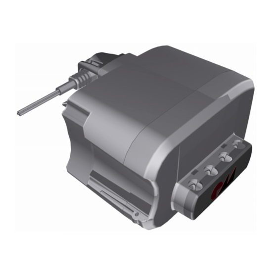
MC10 control unit Description Description The MC10 control unit is a control unit and power supply for one or more DewertOkin drives. A pluggable power cord is used to connect the MC10 control unit to the mains power supply. The MC10 control unit has a non-referenced (unearthed) circuit which is separated from the supply vol- tage by means of doubled reinforced insulation. - Page 12 Description MC10 control unit 4.1.1 Mains power supply connection WARNING Please follow these operating instructions carefully. You could be injured by fire or electrical shock if you do not follow these assembly instructions. The appropriate power cable is included, depending on the regional version (USA, continental Eu- rope, the UK or Australia).
-
Page 13: Technical Specifications
MC10 control unit Technical specifications Technical specifications Mains power supply connection 100 – 240V AC, 50/60Hz Current consumption at nominal opera- Max. 3.15 A (depending on input voltage) tions Mode of operations Intermittent duty 2 minutes /18 minutes Protection class Permitted current consumption of all ad- Max. - Page 14 Technical specifications MC10 control unit Figure 5 Dimensions of the MC10 control unit, top view (in mm) Figure 6 Dimensions of the MC10 control unit, front view (in mm) Figure 7 Dimensions of the MC10 control unit, side view (in mm) 66648 7.0...
-
Page 15: Installation
MC10 control unit Installation Installation Safety notices to observe during installation Basic safety rules must be followed in order to ensure that the end product can be continually ope- rated in a safe manner. These rules must be observed while using the end product and while instal- ling the MC10 control unit. -
Page 16: Installation Procedure
Installation MC10 control unit Installation procedure Before installing the MC10 control unit, make sure that you are observing all of the safety notices found in the "Safety notices to observe during installation" section. 6.2.1 Mounting the MC10 control unit to the MEGAMAT MLZ drive NOTICE The installation length of the MEGAMAT MLZ drive should not be less than 266 mm (installation length of MEGAMAT MLZ drive together with standard clevis). - Page 17 MC10 control unit Installation The MC10 control unit is mounted by snapping it onto the MEGAMAT MLZ drive. CAUTION You should only connect and disconnect the cables when they are completely dis- connected from any live current! 1 Push the MEGAMAT MLZ drive along the guidance groove (D) until the guidance profile (B) snaps onto the support (G).
- Page 18 Installation MC10 control unit Opening the shield cover Figure 9 Opening the shield cover on the MC10 control unit 1 Pull out the mains plug from the outlet. CAUTION You should only connect and disconnect the cables when they are completely dis- connected from any live current! 2 Use a suitable tool to press both locking clips down in the notches as shown in Figure 9.
- Page 19 MC10 control unit Installation 6.2.3 Connecting the pluggable power cord to the MC10 control unit WARNING Please follow these operating instructions carefully. You could be injured by fire or electrical shock if you do not follow these assembly instructions. The appropriate power cable is included, depending on the regional version (USA, continental Eu- rope, the UK or Australia).
- Page 20 Installation MC10 control unit The pluggable power cord should be attached to the power socket (D) located on the rear of the control unit. 1 Pull out the mains plug from the outlet. CAUTION You should only connect and disconnect the cables when they are completely dis- connected from any live current! 2 Remove the cap (B) from the socket.
- Page 21 MC10 control unit Installation 6.2.5 Optional: Mounting the control unit with the adapter Mounting the adapter on the control unit Figure 11 Mounting the adapter on the MC10 control unit 1 Mount the optional adapter to the control unit using four screws (according to DIN 7981: 3.9 mm diam.
- Page 22 Installation MC10 control unit 124.5 108.5 Figure 12 Mounting dimensions of the adapter. View from below (in mm) 1 The control unit is screwed onto the end product by using four screws for the four mounting points (e.g. DIN 7981 screws with 4.8 mm diameter and suitable length of 6 mm plus screw-in depth) as shown in Figure 13.
-
Page 23: Operating Notes
MC10 control unit Operating notes Operating notes The factual information contained within may be used when you are creating the end-product ma- nual. The installation instructions do not contain all information required for the safe operation of the end product. They only describe the assembly and operation of the MC10 control unit as a par- tially assembled piece of machinery. - Page 24 Operating notes MC10 control unit Avoiding electrical risks WARNING Make sure that all live (current-carrying) parts of the drive system and power supply cannot be touched. In particular, be sure that unused power and control unit connec- tions are covered adequately. Power cable WARNING Please follow these operating instructions carefully.
- Page 25 MC10 control unit Operating notes Emergency shut off of a connected drive or control unit CAUTION In an emergency, disconnect the MC10 control unit's power plug in order to shut off the connected drive. The power plug must always be accessible during operations so that it is possible to shut down the drive or control unit at any time.
-
Page 26: Troubleshooting
Troubleshooting MC10 control unit Troubleshooting This chapter describes troubleshooting methods for fixing problems. If you experience an error that is not listed in this table, please contact your supplier. CAUTION Only qualified specialists who have received electrician training should carry out trou- bleshooting and repairs. -
Page 27: Maintenance
MC10 control unit Maintenance Maintenance You should only use spare parts which have been manufactured or approved by DewertOkin. Only these parts will guarantee a sufficient level of safety. Maintenance Type of check Explanation Time interval Check the function and safety A qualified electrician should carry Periodic inspections can of the electrical system. -
Page 28: Cleaning And Care
Maintenance MC10 control unit Cleaning and care The MC10 control unit was designed so that it would be easy to clean. Its smooth surfaces simplify the cleaning process. NOTICE Never clean the MC10 control unit in an automated washing system or with a high- pressure cleaner. -
Page 29: 10. Disposal
MC10 control unit Disposal 10. Disposal 10.1 Packaging material The packaging material should be sorted into recyclable components and then disposed of in ac- cordance with the appropriate national environmental regulations (in Germany according to the re- cycling law KrWG from 01.06.2012; internationally according to the EU Directive 2008/98/EC (Was- te Framework Directive WFD as of 12.12.2008)). -
Page 30: Eu Declaration Of Conformity
EU Declaration of Conformity EG-Konformitätserklärung In compliance with Appendix IV of the EMC-Directive Nach Anhang IV der EMV-Richtlinie 2014/30/EU 2014/30/EU In compliance with Appendix IV of the LVD-Directive Nach Anhang IV der EU-Niederspannungsrichtlinie 2014/35/EU 2014/35/EU Nach Anhang VI der RoHS-Richtlinie 2011/65/EU In compliance with Appendix VI of the EU RoHS (inkl. -
Page 31: Additional Information
Additional information MC10 Control Unit The following standards and norms were used in the versions with at least IPX4 and higher - in according to: EN 60601-1:2006 + A1:2013, IEC 60601-1:2005 + A1:2012 (short description: Edition 3.1), Medical electrical equipment. EN 60601-1-2:2015, IEC 60601-1-2:2014 (short description: Edition 4.0), EMC IEC/EN60601-1, Section 4 General requirements... - Page 32 Additional information MC10 Control Unit The following standards and norms were used in the versions with at least IPX4 and higher - in according to: EN 60601-2-52, IEC 60601-2-52, (Particular requirements for the safety and essential performance of medical beds) IEC/EN 60601-2-52, Section 201.6.2 Protection against electrical shock: Protection class II IEC/EN 60601-2-52, Section...
- Page 33 DewertOkin GmbH Weststrasse 1 Kirchlengern 32278, Germany Tel: +49 (0)5223/979-0 Fax.: +49 (0)5223/75182 http://www.dewertokin.de Info@dewertokin.de ID No.: 66648...
Need help?
Do you have a question about the DewertOkin MC10 and is the answer not in the manual?
Questions and answers