
Related Manuals for Phoenix Mecano Dewert Okin ACCUCONTROL 4.5


Summary of Contents for Phoenix Mecano Dewert Okin ACCUCONTROL 4.5
- Page 1 Control unit ACCUCONTROL 4.5 ACCUCONTROL 4.5DC Installation Instructions (Translation of the original installation instructions)
-
Page 3: Foreword
ACCUCONTROL Foreword Foreword Document revision history Version Date 04/2016 Disclaimer and exclusion of liability DewertOkin is not responsible for damage resulting from: • failure to observe these instructions, • changes made to this product which have not been approved by DewertOkin, or •... -
Page 4: Notice For Customers In Eu Nations
Foreword ACCUCONTROL Notice for customers in EU nations German Inspection Authority (TÜV SÜD Product Service) testing label The construction of the ACCUCONTROL has been inspected by the German TÜV SÜD Product Service Inspection Authority. TÜV SÜD Product Service also monitors the production of the ACCUCONTROL. -
Page 5: Table Of Contents
ACCUCONTROL Table of contents Table of contents Foreword Document revision history Disclaimer and exclusion of liability Manufacturer's address Creation of a complete operating instruction manual for the entire end product Usage in medical products Notice for customers in EU nations Table of contents General Information Configurations... - Page 6 Table of contents ACCUCONTROL Operating notes General information Programming the over-current shutdown mechanism when commissioning the system ACCU Removing the ACCU from the CONTROL Charging the ACCU AC 4.5 and ACCU AC 4.5DC Control panel on the CONTROL Buttons and indicators on the IPROXX handset (an example) Emergency-stop switch Troubleshooting Maintenance...
-
Page 7: General Information
ACCUCONTROL General Information General Information Configurations Both ACCUCONTROL models (4.5 and 4.5DC) are referred to here by the name AccuControl, unless reference is being made to a model-specific feature. This also applies to the CONTROL 4.5 and CONTROL 4.5DC (both referred to by the name CONTROL) as well as ACCU 4.5 and ACCU 4.5DC (both referred to by the name ACCU). -
Page 8: Safety Notices
Safety notices ACCUCONTROL Safety notices Proper and intended usage The ACCUCONTROL control unit is intended to be used as a control unit and battery-operated power supply for the appropriate DewertOkin drive systems in use • for care purposes, • or in hospitals. CAUTION The ACCUCONTROL should only be used for the applications described above. -
Page 9: Selection And Qualification Of Personnel
ACCUCONTROL Safety notices Using the drive systems in medical applications This DewertOkin product complies with the safety requirements found in IEC 60601-1. We strongly recommend that the end product (including all its components) which you are manu- facturing for a medical application should also comply with the safety requirements found in IEC 60601-1. -
Page 10: Product Labelling
Safety notices ACCUCONTROL 2.3.3 Shutting down in an emergency CAUTION In an emergency, the control unit can be shut down by pressing the emergency-stop button. The emergency-stop button must always be accessible during operations so that it can be quickly pressed in an emergency. Product labelling 2.4.1 Ratings plate (type label) - Page 11 ACCUCONTROL Safety notices Figure 3 Ratings plate for the ACCU AC 4.5.5 and ACCU AC 4.5DC (examples) ACCU AC 4.5 Type designations ACCU AC 4.5DC yyyyy Article number Input voltage 4.5 Ah Electrical charge Prod.date Calendar week / year Serial No. Serial number IP20/54 Protection degree...
- Page 12 Safety notices ACCUCONTROL Figure 4 Ratings plate examples for the CONTROL AC 4.5 BAS and CONTROL AC 4.5DC CONTROL AC 4.5 BAS Type designations CONTROL AC 4.5DC BAS zzzzz Article number Input voltage Max. 8.50A Current consumption Duty cycle: 2 min ON / 18 min OFF Intermittent operations: 2 minutes / 18 minutes Prod.date Calendar week / year...
-
Page 13: Possible Combinations
ACCUCONTROL Possible combinations Possible combinations NOTICE In the product name, DC stands for Direct Charging. The CONTROL AC 4.5DC may only be used with the ACCU AC 4.5DC. The ACCUCONTROL can be combined with various components. The following basic combina- tions are possible: •... -
Page 14: Overview Of The Components
Possible combinations ACCUCONTROL Overview of the components 3.2.1 ACCUCONTROL 4.5 (with 1 or 2 motors) ACCUCONTROL 4.5 com- bined with: • MEGAMAT P or GIGAMAT stroke motor • IPROXX Optional: • MEGAMAT XSZ spreader motor 3.2.2 ACCUCONTROL 4.5DC (with 1 motor) ACCUCONTROL 4DC com- bined with: •... -
Page 15: Iproxx Handset
ACCUCONTROL Possible combinations IPROXX handset The following illustrations show the IPROXX handsets that can be used in the different models. 3.3.1 Models Basic IPROXX IPROXX 2 3.3.2 Professional model IPROXX 59245(e) -
Page 16: Description
Description ACCUCONTROL Description The ACCUCONTROL is used for supplying power to and controlling one or more DewertOkin drives. We reserve the right to make unannounced technical changes in the course of our continual product improvement process! Components The AccuControl consists of the ACCU and CONTROL components, with connection ports for drives, the IPROXX handset and the PLUG-IN CHARGER. -
Page 17: Technical Specifications
ACCUCONTROL Technical specifications Technical specifications CONTROL AC 4.5DC / CONTROL AC 4.5 BAS and PRO models Input voltage 24 V DC Input current for the "BAS" model Max. 7.0 A DC Input current for the "PRO" model Max. 8.5 A DC Mode of operations Intermittent duty 2 min./18 min. - Page 18 Technical specifications ACCUCONTROL Dimensions and weight Length x width x height ACCUCONTROL 368 mm x 120 mm x 107 mm CONTROL without mounting rail 120.6 mm x 120 mm x 107.6 mm ACCU 272.2 mm x 120 mm x 89.9 mm Weight ACCUCONTROL Approx.
- Page 19 ACCUCONTROL Technical specifications 272.7 Figure 6 Dimensions of the ACCUCONTROL, top view (in mm) Figure 7 Dimensions of the ACCUCONTROL, side view (in mm) 59245(e)
-
Page 20: Installation
Installation ACCUCONTROL Installation Safety notices to observe during installation Basic safety rules must be followed in order to ensure that the end product can be continually op- erated in a safe manner. These rules must be observed while using the end product and while in- stalling the ACCUCONTROL in the end product. -
Page 21: Installation Procedure
ACCUCONTROL Installation Installation procedure Before installing and connecting the ACCUCONTROL, make sure that you are observing all of the safety notices found in the "Safety notices to observe during installation" section. 6.2.1 Installation and dismounting for the control unit The ACCUCONTROL can be bolted to the end product by using two suitable bolts in the two mounting points on the mounting rail. - Page 22 Installation ACCUCONTROL 6.2.2 Installing the CONTROL mounting rail on the patient lifter Figure 9 Installing on the patient lifter A CONTROL B Mounting points C patient lifter Proceed as described below when installing the ACCUCONTROL on the patient lifter: NOTICE There must be enough available space to mount the unit! 1 Mark both mounting points on the patient lifter.
- Page 23 ACCUCONTROL Installation Figure 10 Inserting the ACCU in the CONTROL A CONTROL B ACCU C Mounting rail D Housing guide tabs 59245(e)
- Page 24 Installation ACCUCONTROL Figure 11 ACCUCONTROL on the patient lifter A ACCUCONTROL B Patient lifter C Drive 59245(e)
- Page 25 ACCUCONTROL Installation 6.2.3 Electrical connection Routing the electrical cables When routing the cables, be sure that: • the cables cannot get jammed, • no mechanical load (such as pulling, pushing or bending) will be put on the cables, and • the cables cannot be damaged in any way. Fasten all cables (especially the connecting cables) to the end product using sufficient kink preven- tion methods.
-
Page 26: Operating Notes
Operating notes ACCUCONTROL Operating notes The factual information contained within may be used when you are creating the end-product man- ual. The installation instructions do not contain all information required for the safe operation of the end product. They only describe the assembly and operation of the ACCUCONTROL as a partially assembled piece of machinery. - Page 27 ACCUCONTROL Operating notes Power-on time / intermittent operations The ACCUCONTROL has been designed for intermittent operations. Intermittent operation is an operational mode where the drive must pause after a specified maximum period of operation (power-on time). This protects the drive from overheating. Extreme overheating can cause a mal- function.
-
Page 28: Programming The Over-Current Shutdown Mechanism When Commissioning The System
Operating notes ACCUCONTROL Programming the over-current shutdown mechanism when commissioning the system NOTICE • This programming must be carried out by the manufacturer of the end product. Do not forward the following description of action on to the end user. •... -
Page 29: Accu
ACCUCONTROL Operating notes ACCU 7.3.1 General safety instructions for the ACCU • Do not open or destroy the ACCU. • The ACCU should only be charged as shown in Figure 16, Figure 18 and Figure 21 (pages 34, 36 and 39). •... - Page 30 Operating notes ACCUCONTROL Figure 13 Inserting the ACCU in the CONTROL A CONTROL B ACCU C Mounting rail D Housing guide tabs The ACCU should not be used for at least 1 hour before changing the battery. 2 Slide the ACCU on the mounting rail (as shown in Figure 13) until it clicks into place. The hous- ing guide tabs (D) must enclose the mounting rail to ensure a tight fit.
-
Page 31: Removing The Accu From The Control
ACCUCONTROL Operating notes Removing the ACCU from the CONTROL 1 Move the patient lifter into its starting position. 2 Press the emergency-stop button and remove all plugs from the sockets of the CONTROL. Figure 14 Releasing the ACCU A patient lifter B ACCU C Mounting rail D Release lever... -
Page 32: Charging The Accu Ac 4.5 And Accu Ac 4.5Dc
Operating notes ACCUCONTROL Charging the ACCU AC 4.5 and ACCU AC 4.5DC The ACCU AC 4.5 and the ACCU AC 4.5DC are charged with the PLUG-IN CHARGER PB 4.5. Charging can be carried out as follows: Charging directly Charging with the Charging at the end product on the ACCU charging station... - Page 33 ACCUCONTROL Operating notes 7.5.1 Charging directly on the ACCU using the PLUG-IN CHARGER PB 4.5 Figure 15 Connection ports and ventilation holes on the ACCU A ACCU B Ventilation holes in the ACCU C Connection sockets for the PLUG-IN CHARGER PB 4.5 1 The ACCU should not be used for at least 1 hour before it is removed from the mounting rail.
- Page 34 Operating notes ACCUCONTROL NOTICE Make sure that the ACCU is in the correct position while charging. The ACCU may only be loaded when it is resting on its base (as shown in Figure 16). Do not place the ACCU upside down during charging. Figure 16 Charging position of the ACCU AC 4.5 and ACCU AC 4.5DC 59245(e)
- Page 35 ACCUCONTROL Operating notes Figure 17 The ACCU AC 4.5 and the ACCU AC 4.5DC are charged directly with the PLUG-IN CHARGER PB 4.5. A PLUG-IN CHARGER PB 4.5 B Plug for the PLUG-IN CHARGER PB 4.5 C ACCU AC 4.5 or ACCU AC 4.5DC D Mains plug 3 Connect the PLUG-IN CHARGER PB 4.5 to the ACCU (as shown in Figure 17).
- Page 36 Operating notes ACCUCONTROL 7.5.2 Charging the ACCU AC 4.5 and ACCU AC 4.5DC at the charging station 1 The ACCU should not be used for at least 1 hour before it is removed from the mounting rail. 2 Remove the ACCU from the mounting rail (as described in section 7.4). NOTICE Make sure that the ACCU is in the correct position while charging.
- Page 37 ACCUCONTROL Operating notes Figure 19 Inserting the ACCU AC 4.5 and ACCU AC 4.5DC in the charging station A Charging station B ACCU C Mounting rail D Housing guide tabs 3 Slide the ACCU on the charging station (as shown in Figure 19) until it clicks into place. The housing guide tabs must enclose the mounting rail to ensure a tight fit.
- Page 38 Operating notes ACCUCONTROL Figure 20 Charging the ACCU AC 4.5 and ACCU AC 4.5DC at the charging station A PLUG-IN CHARGER PB 4.5 B Plug for the PLUG-IN CHARGER PB 4.5 at the charging station C Charging station D ACCU 5 Connect the PLUG-IN CHARGER PB 4.5 to the charging station (as shown in Figure 20).
- Page 39 ACCUCONTROL Operating notes 7.5.3 Charging the ACCU AC 4.5DC directly at the patient lifter The ACCU AC 4.5DC can only be charged with the CONTROL AC 4.5DC! No motion functions are possible during the charging! Figure 21 Charging the ACCU AC 4.5DC at the CONTROL AC 4.5DC A PLUG-IN CHARGER PB 4.5 B Y-cable (for system with 2 motors) C ACCU AC 4.5DC...
-
Page 40: Control Panel On The Control
Operating notes ACCUCONTROL Control panel on the CONTROL The control panel on the CONTROL has a reset button and a display showing the charge state and a service indicator. Figure 22 Control panel on the CONTROL A Control panel on the CONTROL AC 4.5 B Control panel on the CONTROL AC 4.5 PRO and the CONTROL AC 4.5DC PRO BAS and the CONTROL AC 4.5DC BAS... - Page 41 ACCUCONTROL Operating notes 7.6.1 Maintenance when red light at service display If the service display is lit red, we recommend replacing or checking the following components: Component Measure / Action DEWERT drive • Visual inspection of cables and connectors • Visual inspection for housing damage •...
-
Page 42: Buttons And Indicators On The Iproxx Handset (An Example)
Operating notes ACCUCONTROL Buttons and indicators on the IPROXX handset (an example) Custom IPROXX handsets can be delivered for use with the patient lifter. The IPROXX PRO model is used for the example below. (For the IPROXX BAS handset, there is no reset function, no over- current shutdown, and no service or battery charge indicators). -
Page 43: Emergency-Stop Switch
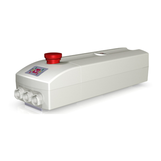
ACCUCONTROL Operating notes Emergency-stop switch The emergency-stop switch deactivates all functionality. Figure 24 Emergency-stop switch for the CONTROL AC 4.5 / CONTROL AC 4.5DC A Emergency-stop switch 59245(e) -
Page 44: Troubleshooting
Troubleshooting ACCUCONTROL Troubleshooting This chapter describes troubleshooting methods for fixing problems. If you experience an error that is not listed in this table, please contact your customer representative. CAUTION Only qualified specialists who have received electrician training should carry out trou- bleshooting and repairs. -
Page 45: Maintenance
ACCUCONTROL Maintenance Maintenance You should only use spare parts which have been manufactured or approved by DewertOkin. Only these parts will guarantee a sufficient level of safety. Maintenance Type of check Explanation Time interval Make sure that no drive The inspection may only be car- At least every six months. -
Page 46: Cleaning And Care
Maintenance ACCUCONTROL Cleaning and care The ACCUCONTROL is easy to clean. Its smooth surfaces simplify the cleaning process. NOTICE Never clean the ACCUCONTROL in an automated washing system or with a high- pressure cleaner. Do not allow fluids to penetrate the lighting. Damage to the system could result. -
Page 47: 10. Disposal
ACCUCONTROL Disposal 10. Disposal 10.1 Packaging material The packaging material should be sorted into recyclable components and then disposed of in ac- cordance with the appropriate national environmental regulations (in Germany according to the re- cycling law KrWG from 01.06.2012; internationally according to the EU Directive 2008/98/EC (Waste Framework Directive WFD as of 12.12.2008)). -
Page 48: Eu Declaration Of Conformity
EU Declaration of Conformity EG-Konformitätserklärung Nach Anhang IV der EMV-Richtlinie 2014/30/EU In compliance with Appendix IV of the EMC-Directive 2014/30/EU In compliance with Appendix IV of the LVD-Directive Nach Anhang IV der EU-Niederspannungsrichtlinie 2014/35/EU 2014/35/EU Nach Anhang VI der RoHS-Richtlinie 2011/65/EU In compliance with Appendix VI of the EU RoHS (inkl. -
Page 49: Additional Information
Additional information The following standards have been applied for the patient lifter as used for transporting patients with handicaps – in accordance with ISO 10535:2006 "Medical electrical equipment": ISO 10535, Section 4.3.1.24 Protection: min IPX4 ISO 10535, Section 4.3.1.17 Control with button ISO 10535, Section 4.3.1.14 Easy-to-use controls ISO 10535, Section 4.3.1.15... - Page 50 The following standards have applied for the models ACCUCONTROL 4.5 BAS, ACCUCONTROL 4.5DC BAS, ACCUCONTROL 4.5 PRO and ACCUCONTROL 4.5DC PRO with min IPX4 – in ac- cordance with EN 60601-2-52:2010 and IEC 60601-2-52:2009 "Particular requirements for the safety and essential performance of medical beds": EN 60601-2-52, Section 201.7.6.3 Control keypad symbols (depending on the cus- tomer's requirements)
- Page 52 DewertOkin GmbH Weststrasse 1 Kirchlengern 32278, Germany Tel: +49 5223/979-0 Fax.: +49 5223/75182 http://www.dewertokin.de Info@dewertokin.de ID No.: 59245...
Need help?
Do you have a question about the Dewert Okin ACCUCONTROL 4.5 and is the answer not in the manual?
Questions and answers