Table of Contents
Advertisement
Available languages
Available languages
Quick Links
Advertisement
Chapters
Table of Contents

Related Manuals for Riello BGK1


Summary of Contents for Riello BGK1
- Page 1 Installation, use and maintenance instructions Instrucciones de instalación, uso y mantenimiento Light oil burners Quemadores de gasóleo One stage operation Funcionamiento a 1 llama CODE - CÓDIGO MODEL - MODELO 3737006 - 3737066 BGK1 3737456 BGK2 20012189 BGK3 20136520 (2) - 05/2018...
- Page 2 Original instructions Instructions originales...
-
Page 3: Table Of Contents
Contents Declaration....................................3 Information and general warnings............................4 Information about the instruction manual ........................4 2.1.1 Introduction.................................. 4 2.1.2 General dangers................................4 2.1.3 Other symbols ................................4 2.1.4 Delivery of the system and the instruction manual...................... 5 Guarantee and responsibility............................5 Safety and prevention................................ - Page 4 Contents Operating programme ..............................24 Table of times ................................25 7.7.1 Operating status indication ............................25 7.7.2 Fault diagnostics - lockouts............................26 7.7.3 Fuel preheating function ............................26 7.7.4 Shutdown test ................................26 7.7.5 Intermittent operation ..............................26 7.7.6 Recycle and limit of repetitions ..........................26 7.7.7 Presence of an extraneous light or parasite flame.....................27 7.7.8 Pre and post-ignition of the discharge of the ignition transformer................27 7.7.9...
-
Page 5: Declaration
BGK3 CO max: 31 mg/kWh Max. NOx: 70 mg/kWh Manufacturer's Declaration RIELLO S.p.A. declares that the following products comply with the NOx emission limits specified by German standard “1. BImSchV revision 26.01.2010”. Product Type Model Output Light oil burners 370T1 BGK1 17.8 - 35.6 kW... -
Page 6: Information And General Warnings
Information and general warnings Information and general warnings Information about the instruction manual 2.1.1 Introduction DANGER: EXPLOSION The instruction manual supplied with the burner: This symbol signals places where an explosive at- is an integral and essential part of the product and must not mosphere may be present. -
Page 7: Delivery Of The System And The Instruction Manual
Information and general warnings 2.1.4 Delivery of the system and the instruction The system supplier must carefully inform the user about: - the use of the system; manual - any further tests that may be required before activating the When the system is delivered, it is important that: system;... -
Page 8: Safety And Prevention
Safety and prevention Safety and prevention Introduction The burners have been designed and built in compliance with the type and pressure of the fuel, the voltage and frequency of the current regulations and directives, applying the known technical electrical power supply, the minimum and maximum deliveries for rules of safety and envisaging all the potential danger situations. -
Page 9: Technical Description Of The Burner
Standard head Extended head Electrical supply 1/230/50 1/230V/50Hz of the system : 1/220/60 1/220V/60Hz 1/230/50 BASIC DESIGNATION EXTENDED DESIGNATION 1/230/50 Models available Designation Combustion head Voltage Code BGK1 1/230/50 3737006 - 3737066 BGK2 1/230/50 3737456 BGK3 1/230/50 20012189 Tab. A 20136520... -
Page 10: Technical Description Of The Burner
Technical description of the burner Technical data Model BGK1 BGK2 BGK3 1.5 3.0 2.7 5.0 3.8 6.15 Delivery kg/h 17.8 35.6 32 59.3 45.0 73.0 Thermal power Fuel Light oil, viscosity 4 6 mm /s at 20°C Operation Intermittent (FS1) -
Page 11: Maximum Dimensions
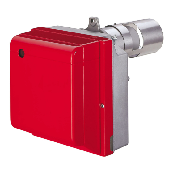
Maximum dimensions The maximum dimensions of the flange and burner are given in Fig. 1. D7217 Fig. 1 Ø Ø Type BGK1 BGK2 BGK3 Burner description S9660 Fig. 2 Oil pump To meet the required standards, the burner must Air damper adjustment assembly be protected by a pane or by the boiler door. -
Page 12: Firing Rate
1013 mbar (about 0 m a.s.l.) and with the com- bustion head regulated as indicated on page 20. WARNING WARNING BGK1 BGK2 Light oil output – kg/h D7241 Heat output – kW... -
Page 13: Electrical Control Box
Technical description of the burner Electrical control box The control box is a control and supervision system for forced To remove the control box from the burner it is necessary to (Fig. draught burners, for intermittent operation (at least one controlled shutdown every 24 hours). -
Page 14: Installation
Installation Installation Notes on safety for the installation After carefully cleaning all around the area where the burner is to The installation of the burner must be carried out be installed, and arranging for the environment to be illuminated by qualified personnel, as indicated in this manual correctly, proceed with the installation operations. -
Page 15: Preliminary Checks
Installation Preliminary checks Checking the consignment After removing all the packaging, check the integ- rity of the contents. In the event of doubt, do not use the burner; contact the supplier. CAUTION The packaging elements (wooden cage or card- D9370 board box, nails, clips, plastic bags, etc.) must not Fig. -
Page 16: Securing The Burner To The Boiler
Installation Securing the burner to the boiler Provide an adequate lifting system of the burner. With some boilers it is possible that the CO values exceed those stated in this manual. To lower these emissions it is necessary to use the recircu- lating pipe supplied. -
Page 17: Combustion Head Adjustment
4)(Fig. 11). When the adjustment is completed screw in the nut 5) again. For burners BGK1 and BGK3: when the burner shuts down the air damper automatically closes, up to a max. flue depression of 0.5 mbar. -
Page 18: Electrodes Setting
Installation Electrodes setting To adjust, proceed as follows: rest the diffuser disc-holder assembly 3)(Fig. 12) against the These dimensions Fig. 12 must be respected. nozzle holder 2)(Fig. 12) and lock it in place with the screw 4)(Fig. 12). WARNING For any adjustments of the electrodes assembly 5), loosen screw 6)(Fig. -
Page 19: Maintenance Position
Installation 5.12 Maintenance position There are two ways to access the nozzle, the diffuser disc and 2nd Method (Fig. 13): the electrodes: unscrew and remove the fixing nut to the flange and remove the burner from the boiler. 1st Method (Fig. 13): ... -
Page 20: Hydraulic Systems
Installation 5.13 Hydraulic systems 5.13.1 Combustion supply Explosion danger due to fuel leaks in the pres- The burner is designed to allow entry of the flexible oil lines on ence of a flammable source. either side of the burner. Precautions: avoid knocking, attrition, sparks and Depending on whether the pipe outlet is to the right or left of the heat. -
Page 21: Pressure Adjustment
Installation 5.13.3 Pressure adjustment 5.13.6 Vacuum systems The pump leaves the factory set at 12 bar. Vacuum systems (Fig. 19 and Fig. 20) have a negative fuel pres- If necessary, recalibrate the pressure using the screw 5) sure (depression) on intake to the burner. Usually the tank is low- (Fig. -
Page 22: Start-Up, Calibration And Operation Of The Burner
Start-up, calibration and operation of the burner Start-up, calibration and operation of the burner Notes on safety for the first start-up The first start-up of the burner must be carried out Check the correct working of the adjustment, com- by qualified personnel, as indicated in this manual mand and safety devices. -
Page 23: Recommended Nozzles
Start-up, calibration and operation of the burner Recommended nozzles The burner complies with the emission requirements of the EN 267 standard. In order to guarantee that emissions do not vary, recommended and/or alternative nozzles specified by manufacturer in the In- struction and warning booklet should be used. -
Page 24: Electrical System
Start-up, calibration and operation of the burner Electrical system Notes on safety for the electrical wiring The electrical wiring must be carried out with the electrical supply disconnected. Electrical wiring must be made in accordance with the regulations currently in force in the country of destination and by qualified personnel. -
Page 25: Electrical Diagram
Start-up, calibration and operation of the burner Electrical diagram 20139658 TO BE DONE BY BY THE INSTALLER Master switch 230V ~ 50Hz Fig. 22 KEY TO LAY-OUT: Do not invert the neutral with the phase in the – 2nd stage operation signal (230V - 0.1A max.) electrical supply line. -
Page 26: Operating Programme
Start-up, calibration and operation of the burner Operating programme Normal operation Lockout due to extraneous light during pre-purging 20136229 POWER SUPPLY POWER SUPPLY Green blink Lockout Green Orange Green blink blink Orange blink L E D Green Red, green blink Red blinking No flame during operation blink... -
Page 27: Table Of Times
Start-up, calibration and operation of the burner Table of times Symbol Description Value (sec.) Standby: the burner is waiting for a heat request Standby time for an input signal: reaction time, control box remains in waiting mode for t1 Flame or flame simulation detected before demand for heat: the control box remains idle. 4.5 Initialisation standby time: checking time following the main power start-up Checks extraneous light or parasite flame during t2: waiting mode for t2l, then lockout: the motor... -
Page 28: Fault Diagnostics - Lockouts
Start-up, calibration and operation of the burner 6.7.2 Fault diagnostics - lockouts Fault description Reset button colour Seconds Colour code GREEN, RED Extraneous light (false flame signal) blinking alternately ORANGE Electrical power voltage fault slow blinking Electrical power frequency fault ORANGE ORANGE, GREEN Flame control voltage fault... -
Page 29: Presence Of An Extraneous Light Or Parasite Flame
Start-up, calibration and operation of the burner 6.7.7 Presence of an extraneous light or parasite 6.7.10 Protection reset flame The burner can be reset only 5 times consecutively, then power supply has to be disconnected for a new 5 reset possibilities. The presence of the parasite flame or the extraneous light can be The burner can only be reset if power supply is applied to the con- detected in the standby condition when the burner is stopped and... -
Page 30: Frequency Supply Error
Start-up, calibration and operation of the burner 6.7.15 Frequency supply error 6.7.20 Post-purging The control box automatically detects the value of the frequency Post-purging is a function that allows you to maintain the air purg- of the main supply in the range of 50 - 60 Hz, in both cases work- ing even after the burner is switched off in the absence of the heat ing times are verified. -
Page 31: Lockout Log
Start-up, calibration and operation of the burner 6.7.23 Lockout log In the event of burner applications with remote The control box allows the logging of the type and number of lock- control commands greater than those indicated in outs that have occurred and keeps them even without the electri- Tab. -
Page 32: Automatic Pre-Heating Deactivation
Start-up, calibration and operation of the burner Automatic pre-heating deactivation It is possible to disable the pre-heater function in automatic mode by pressing the remote reset button. Sequence of pre-heating Colour of the led deactivation of the button Allow the disabling of the pre-heating only when there is no lockout or fault Permit the disabling of the pre-heating using the remote reset button. -
Page 33: Programming Menu
Start-up, calibration and operation of the burner Programming menu 6.9.1 General notes If the number of presses on the reset or remote reset button ex- ceeds the maximum allowable, the value that stays in memory The programming menu can be accessed via the integrated reset will be the maximum one. -
Page 34: Shutdown Test
Start-up, calibration and operation of the burner 6.9.3 Shutdown test after flame disappearance during operation after disconnecting and reconnecting the electrical supply Sequence for shut-down test programming Programming allowed in OPERATING mode and in STAND- 6.9.6 Setting a long pre-purging ... -
Page 35: Resetting The Programming Menu Parameters And The Lockout Log
Start-up, calibration and operation of the burner 6.9.8 Resetting the programming menu parameters GREEN led OFF Press the button 1 time to reset the lockout log (*) and the lockout log Press the button 2 times to reset the number of lockouts (*) The control box allows you to reset the log and the number of ... -
Page 36: Maintenance
Maintenance Maintenance Notes on safety for the maintenance Filters Clean the filter of the fuel suction line and of the pump. The periodic maintenance is essential for the good operation, If rust or other impurities are observed inside the pump, use a safety, yield and duration of the burner. -
Page 37: Faults / Solutions
Faults / Solutions Faults / Solutions Here below you can find some causes and the possible solutions When lockout lamp comes on the burner will attempt to light only for some problems that could cause a failure to start or incorrect after pushing the reset button. -
Page 38: Appendix - Accessories
Appendix - Accessories Appendix - Accessories PC interface kit Burner Code All models 3002731 Light oil filter kit Filtration grade Burner Code (m) 3006561 All models 3075011 Line filter kit Filtration grade Burner Code (m) All models 3000926 7-pin plug kit Burner Code All models... - Page 39 Índice Declaración ....................................3 Informaciones y advertencias generales ..........................4 Información sobre el manual de instrucciones ......................4 2.1.1 Introducción................................. 4 2.1.2 Peligros generales............................... 4 2.1.3 Otros símbolos ................................4 2.1.4 Entrega de la instalación y del manual de instrucción ....................5 Garantía y responsabilidades............................
- Page 40 Índice Programa de funcionamiento .............................24 Tabla de los tiempos ..............................25 7.7.1 Indicación del estado de funcionamiento ........................25 7.7.2 Diagnóstico anomalías - bloqueos ..........................26 7.7.3 Función de pre-calentamiento del combustible ......................26 7.7.4 Ensayo de apagado ..............................26 7.7.5 Funcionamiento intermitente............................26 7.7.6 Reciclado y límite de repeticiones ..........................26 7.7.7 Presencia de luz extraña o llama parásita .........................27 7.7.8...
-
Page 41: Declaración
CO máx: 31 mg/kWh NOx máx: 70 mg/kWh Declaración del fabricante RIELLO S.p.A. declara que los siguientes productos respetan los valores límite de emisiones de NOx establecidos por la norma- tiva alemana “1. BImSchV revisión 26.01.2010”. Producto Tipo Modelo Potencia Quemadores de gasóleo... -
Page 42: Informaciones Y Advertencias Generales
Informaciones y advertencias generales Informaciones y advertencias generales Información sobre el manual de instrucciones 2.1.1 Introducción ATENCIÓN ÓRGANOS EN MOVIMIENTO El manual de instrucción entregado como suministro del quema- Este símbolo proporciona informaciones para evi- dor: tar el acercamiento de las extremidades a órga- ... -
Page 43: Entrega De La Instalación Y Del Manual De Instrucción
Informaciones y advertencias generales 2.1.4 Entrega de la instalación y del manual de El proveedor de la instalación informe con precisión al usua- rio acerca de: instrucción - el uso de la instalación, En ocasión de la entrega de la instalación es necesario que: - las eventuales pruebas futuras que pudieran ser necesa- ... -
Page 44: Seguridad Y Prevención
Seguridad y prevención Seguridad y prevención Introducción Los quemadores fueron diseñados y fabricados en conformidad máximos con los cuales está regulado el quemador, la presuriza- con las normas y directivas vigentes, aplicando las regulaciones ción de la cámara de combustión, las dimensiones de la cámara técnicas de seguridad conocidas y previendo todas las situacio- de combustión, la temperatura ambiente, deben estar compren- nes de peligro potenciales. -
Page 45: Descripción Técnica Del Quemador
Cabezal estándar Cabezal largo Alimentación eléctrica 1/230/50 1/230V/50Hz del sistema: 1/220/60 1/220V/60Hz 1/230/50 DESIGNACIÓN BASE DESIGNACIÓN AMPLIADA 1/230/50 Modelos disponibles Designación Cabezal de combustión Tensión Código BGK1 1/230/50 3737006 - 3737066 BGK2 1/230/50 3737456 BGK3 1/230/50 20012189 Tab. A 20136520... -
Page 46: Descripción Técnica Del Quemador
Descripción técnica del quemador Datos técnicos Modelo BGK1 BGK2 BGK3 1,5 3,0 2,7 5,0 3,8 6,15 Caudal kg/h 17,8 35,6 32 59,3 45,0 73,0 Potencia térmica Combustible Gasóleo, viscosidad 4 6 mm /seg. a 20º C Funcionamiento Intermitente (FS1) Empleo Calderas: con agua o aceite diatérmico... -
Page 47: Dimensiones Máximas Totales
Dimensiones máximas totales Las dimensiones del quemador y de la brida se indican en la Fig. 1. D7217 Fig. 1 Ø Ø Tipo BGK1 BGK2 BGK3 Descripción del quemador S9660 Fig. 2 Bomba de aceite Para cumplir con los requisitos reglamentarios in- Grupo de regulación registro de aire... -
Page 48: Campo De Trabajo
(aprox. 0 metros s.n.m.) y con el cabezal de com- ATENCIÓN pre dentro del campo de encendido correspon- bustión regulado como se indica en la pág. 20. diente. ATENCIÓN BGK1 BGK2 Caudal de gasóleo – kg/h D7241 Potencia térmica – kW D9487 BGK3 - 0.2... -
Page 49: Caja De Control Eléctrica
Descripción técnica del quemador Caja de control eléctrica La caja de control es un sistema de control y supervisión de que- Para extraer la caja de control del quemador es necesario (Fig. madores de aire soplado, para el funcionamiento intermitente (al menos un apagado controlado cada 24 horas). -
Page 50: Instalación
Instalación Instalación Notas sobre la seguridad para la instalación Después de realizar una cuidadosa limpieza en toda el área de El quemador debe ser instalado por personal ha- la instalación del quemador y de proveer una correcta ilumina- bilitado según todo lo indicado en el presente ma- ción del ambiente, proceder con las operaciones de instalación. -
Page 51: Controles Preliminares
Instalación Controles preliminares Control del suministro Después de haber quitado todos los embalajes, asegurarse de la integridad del contenido. En caso de dudas no utilizar el quemador y dirigirse al proveedor. PRECAUCIÓN Los elementos del embalaje (jaula de madera o D9370 caja de cartón, clavos, grapas, bolsas plásticas, Fig. -
Page 52: Fijación Del Quemador A La Caldera
Instalación Fijación del quemador a la caldera Prepare un sistema de elevación adecuado del quemador. Es posible que los valores de CO en algunas cal- deras superen los declarados en el presente ma- nual. Para disminuir dichas emisiones, debe utilizarse el tubo de recirculación suministrado en ATENCIÓN dotación. -
Page 53: Regulación Del Cabezal De Combustión
4)(Fig. 11). Después de finalizar la regulación, enroscar nuevamente la tuerca 5). Para los quemadores BGK1 y BGK3: Cuando el quemador se para, el registro de aire se cierra auto- máticamente, hasta una depresión máx. en la chimenea de 0,5 mbar. -
Page 54: Regulación Electrodos
Instalación Regulación electrodos Para realizar la regulación proceder de la siguiente manera: apoyar el conjunto soporte estabilizador 3)(Fig. 12) en el porta- Respetar las medidas de la Fig. 12. boquilla 2)(Fig. 12) y bloquear con el tornillo 4)(Fig. 12). Para posibles ajustes del grupo electrodos 5) aflojar el ATENCIÓN tornillo 6)(Fig. -
Page 55: Posición De Mantenimiento
Instalación 5.12 Posición de mantenimiento Para acceder a la boquilla, al disco estabilizador y a los electro- 2° Modo (Fig. 13): dos, se puede proceder de dos modos: Desenroscar y quitar la tuerca de fijación a la brida para extraer el quemador de la caldera. -
Page 56: Instalaciones Hidráulicas
Instalación 5.13 Instalaciones hidráulicas 5.13.1 Alimentación de combustión Riesgo de explosión a causa de derrame de com- El quemador está preparado para que los tubos de alimentación bustible en presencia de fuentes inflamables. del gasóleo se conecten por ambos lados. Precauciones: evitar golpes, roces, chispas, ca- Según si los tubos salen hacia la derecha o hacia la izquierda del lor. -
Page 57: Regulación De Presión
Instalación 5.13.3 Regulación de presión 5.13.6 Instalaciones por depresión La bomba se calibra en fábrica a 12 bar. Las instalaciones por depresión (Fig. 19 y Fig. 20) presentan una Si es necesario, volver a calibrar la presión con el tornillo 5) presión del combustible negativa (depresión) en la entrada del Fig. -
Page 58: Puesta En Funcionamiento, Calibración Y Funcionamiento Del Quemador
Puesta en funcionamiento, calibración y funcionamiento del quemador Puesta en funcionamiento, calibración y funcionamiento del quemador Notas sobre la seguridad para la primera puesta en funcionamiento La primera puesta en funcionamiento del quema- Comprobar el correcto funcionamiento de los dis- dor debe ser realizada por personal habilitado se- positivos de regulación, mando y seguridad. -
Page 59: Boquillas Aconsejadas
Puesta en funcionamiento, calibración y funcionamiento del quemador Boquillas aconsejadas El quemador está en conformidad con los requerimientos de emi- sión previstos por la norma EN 267. Para garantizar la constancia de las emisiones, se deben utilizar boquillas aconsejadas y/o alternativas indicadas por la Empresa Constructora en las instrucciones y advertencias. -
Page 60: Instalación Eléctrica
Puesta en funcionamiento, calibración y funcionamiento del quemador Instalación eléctrica Notas sobre la seguridad para las conexiones eléctricas Las conexiones eléctricas se deben llevar a cabo con la alimentación eléctrica desconectada. Las conexiones eléctricas se deben realizar según las normas vigentes en el país de destino y por parte de per- sonal cualificado. -
Page 61: Esquema Eléctrico
Puesta en funcionamiento, calibración y funcionamiento del quemador Esquema eléctrico 20139658 A CARGO DEL INSTALADOR Interruptor general 230V ~ 50Hz Fig. 22 LEYENDA: No invertir Neutro con Fase en la línea de ali- – Señal de funcionamiento 2ª llama (230V - 0,1A máx.) mentación eléctrica. -
Page 62: Programa De Funcionamiento
Puesta en funcionamiento, calibración y funcionamiento del quemador Programa de funcionamiento Funcionamiento normal Bloqueo debido a luz extraña durante la pre-ventilación 20136229 ALIMENTACIÓN ALIMENTACIÓN Parpadeo verde Bloqueo Parpadeo Parpadeo Verde verde anaranjado Parpadeo anaranjado L E D Parpadeo Parpadeo verde, rojo Parpadeo ROJO Falta la llama durante el funcionamiento verde... -
Page 63: Tabla De Los Tiempos
Puesta en funcionamiento, calibración y funcionamiento del quemador Tabla de los tiempos Símbolo Descripción Valor (seg) En modo espera: El quemador espera la solicitud de calor Tiempo de espera para una señal de entrada: tiempo de reacción, la caja de control permanece en espera de solicitud por t1 Presencia de llama o simulación de llama antes de requerir calor: la caja de control permanece detenida. -
Page 64: Diagnóstico Anomalías - Bloqueos
Puesta en funcionamiento, calibración y funcionamiento del quemador 6.7.2 Diagnóstico anomalías - bloqueos Color del pulsador de Segun- Descripción del desperfecto Código color desbloqueo VERDE, ROJO Luz extraña o presencia de señal de llama parásita parpadeo alternadamente ANARANJADO Anomalía en la tensión de alimentación eléctrica parpadeo lento Anomalía en la frecuencia de la alimentación eléctrica ANARANJADO... -
Page 65: Presencia De Luz Extraña O Llama Parásita
Puesta en funcionamiento, calibración y funcionamiento del quemador 6.7.7 Presencia de luz extraña o llama parásita 6.7.10 Desbloqueo protección La presencia de llama parásita o de luz extraña puede ser detec- El quemador puede desbloquearse solo 5 veces consecutivas, tada en el estado de standy-by cuando el quemador está parado Después, es necesario desconectar la alimentación para tener y en espera de una solicitud de calor. -
Page 66: Anomalía En La Frecuencia De La Alimentación Principal
Puesta en funcionamiento, calibración y funcionamiento del quemador 6.7.15 Anomalía en la frecuencia de la alimentación 6.7.20 Post-ventilación principal La post-ventilación es la función que permite mantener la venti- lación del aire cuando se apaga el quemador por ausencia de so- La caja de control detecta automáticamente el valor de la fre- cuencia de la alimentación principal en el intervalo de 50 ÷... -
Page 67: Historial De Los Bloqueos
Puesta en funcionamiento, calibración y funcionamiento del quemador 6.7.23 Historial de los bloqueos En el caso de aplicaciones de quemadores con La caja de control permite memorizar el tipo y la cantidad de blo- mando a distancia remotos superiores a los indi- queos que se han presentado y los mantiene en ausencia de ali- cados en Tab. -
Page 68: Desactivación Automática Del Pre-Calentamiento
Puesta en funcionamiento, calibración y funcionamiento del quemador Desactivación automática del pre-calentamiento Es posible deshabilitar la función del pre-calentamiento en modo automático presionando el pulsador de desbloqueo a dis- tancia. Secuencia de deshabilitación del pre- Color del led calentamiento del pulsador Permitir la deshabilitación del pre-calen- tamiento sólo si no hay bloqueos ni ano- malías... -
Page 69: Menú De Programación
Puesta en funcionamiento, calibración y funcionamiento del quemador Menú de programación 6.9.1 General Si el número de presiones en el pulsador de desbloqueo integra- do o a distancia excede el máximo permitido, el valor que perma- Se puede acceder al menú programación mediante el pulsador necerá... -
Page 70: Ensayo De Apagado
Puesta en funcionamiento, calibración y funcionamiento del quemador 6.9.3 Ensayo de apagado Led VERDE ON y OFF cada vez que se presiona y se des- bloquea Secuencia para ensayo de apagado Después de 10 seg. el led VERDE parpadea según las ... -
Page 71: Reset De Los Parámetros Del Menú De Programación Y Del Historial De Bloqueos
Puesta en funcionamiento, calibración y funcionamiento del quemador 6.9.8 Reset de los parámetros del menú de Presionar el pulsador 1 vez para reiniciar el historial de blo- queos (*) programación y del historial de bloqueos Presionar el pulsador 2 veces para reiniciar el n° de blo- La caja de control permite poner en cero el historial y el número queos (*) de bloqueos, las horas de funcionamiento, el número de encen-... -
Page 72: Mantenimiento
Mantenimiento Mantenimiento Notas sobre la seguridad para el Filtros mantenimiento Efectuar la limpieza del filtro del conducto de aspiración del com- bustible y del filtro de la bomba. El mantenimiento periódico es fundamental para el buen funciona- Si en el interior de la bomba se aprecia oxidación u otras impu- miento, la seguridad, el rendimiento y la duración del quemador. -
Page 73: Anomalías / Soluciones
Anomalías / Soluciones Anomalías / Soluciones A continuación se detallan algunas causas y posibles soluciones sador de desbloqueo. Hecho esto, se produce un encendido para algunos problemas que pudieran causar una falla en el en- regular. Se puede imputar la parada a una anomalía transitoria y cendido o un funcionamiento incorrecto del quemador. -
Page 74: Apéndice - Accesorios
Apéndice - Accesorios Apéndice - Accesorios Kit interfaz PC Quemador Código Todos los modelos 3002731 Kit filtro de gasóleo Grado de filtración Quemador Código (m) 3006561 Todos los modelos 3075011 Kit filtro de línea Grado de filtración Quemador Código (m) Todos los modelos 3000926 Kit conector macho de 7 contactos... - Page 76 RIELLO S.p.A. I-37045 Legnago (VR) Tel.: +39.0442.630111 http:// www.riello.it http:// www.riello.com Subject to modifications - Con la posibilidad de modificación...
Need help?
Do you have a question about the BGK1 and is the answer not in the manual?
Questions and answers