Table of Contents
Advertisement
Available languages
Available languages
Quick Links
Advertisement
Chapters
Table of Contents

Related Manuals for Riello 370T1 Series


Summary of Contents for Riello 370T1 Series
- Page 1 Installation, use and maintenance instructions Montage und Bedienungsanleitung Light oil burners Öl-Gebläsebrenner One stage operation Einstufiger Betrieb MODEL TYPE CODE MODELL 3737005 BGK1 370T1 3737405 BGK2 374T1 2903193 (5) - 12/2006...
- Page 2 DECLARATION OF CONFORMITY Royal Decree (A.R.) 8/1/2004 - Belgium Producer: RIELLO S.p.A. Via Pilade Riello, 7 37045 LEGNAGO (VR) Italy Tel. ++39.0442630111 Fax ++39.044221980 Distributed by: RIELLO NV Ninovesteenweg 198 9320 Erembodegem Tel. (053) 769 030 Fax. (053) 789 440 e-mail.
-
Page 3: Table Of Contents
INDEX BURNER DESCRIPTION........... . . Burner equipment . -
Page 4: Burner Description
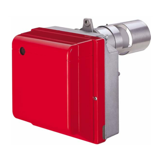
BURNER DESCRIPTION One stage light oil burner with low pollutant emissions (Nitric Oxide NOx, Carbon monoxide CO and unburnt Hydrocarbons). Burner with CE marking in conformity with EEC directives: EMC 89/336/EEC, Low Voltage 73/23/EEC, Machines 98/37/EEC and Efficiency 92/42/EEC. CE Certification No.: 0036 0232/98 (370T1) – 0036 0233/98 (374T1), as 92/42/CEE. The burner meets protection level of IP X0D (IP 40) as EN 60529. -
Page 5: 2.1 Technical Data
TECHNICAL DATA 2.1 TECHNICAL DATA TYPE 370 T1 374 T1 − − Output 3.0 kg/h 5.0 kg/h − − Thermal power 17.8 35.6 kW 59.3 kW Fuel Light oil, viscosity 4 – 6 mm /s at 20 °C ± Electrical supply Single phase, 230 V 50Hz Motor... -
Page 6: Installation
INSTALLATION THE BURNER MUST BE INSTALLED IN CONFORMITY WITH LEGISLATION AND LOCAL STANDARDS. WORKING POSITION The burner is designed for operation in positions 1 and 2 only. Installation 1 is the preferred option as it is the only one that enables maintenance to be performed as described later on in this manual. Operation is possible with installation option 2 though maintenance cannot be performed with the burner con- nected to the boiler. -
Page 7: Hydraulic Systems
HYDRAULIC SYSTEMS WARNING: Fig. 7 The burner is designed to accommodate the installation of light oil supply pipes on either side. It is necessary to install a filter on the fuel supply line. The pump is designed to allow working with two pipes. In order to obtain one pipe working it is necessary to unscrew the return plug (2), remove the by-pass screw (3) and then screw again the plug (2). -
Page 8: Electrical Wiring
ELECTRICAL WIRING NOTES: WARNING – Wires of min. 1 mm section. (Unless requested oth- DO NOT EXCHANGE NEUTRAL WITH PHASE erwise by local standards and legislation). 230V 50Hz – The electrical wiring carried out by the installer must be in compliance with the rules in force in the Country. (See page 5). -
Page 9: Burner Operation
BURNER OPERATION WARNING QUALIFIED PERSONNEL WITH THE RIGHT INSTRUMENTS MUST HANDLE THE BURNER'S FIRST START-UP COMBUSTION ADJUSTMENT In conformity with Efficiency Directive 92/42/EEC the application of the burner on the boiler, adjustment and testing must be carried out observing the instruction manual of the boiler, including verification of the CO and concentration in the flue gases, their temperatures and the average temperature of the water in the boiler. -
Page 10: Maintenance Position
MAINTENANCE POSITION, (fig. 11) Fig. 11 Before performing maintenance on the burner, it is best to disconnect the system’s power supply. Unscrew and remove the screw fastening it to the flange to take the burner off the boiler. Hook the burner onto flange (7), loosen screws (5) and pull off the blast tube assembly (4). -
Page 11: Electrode Positioning
ELECTRODES ADJUSTMENT, (see fig. 14) To reach the electrodes, proceed as Fig. 14 described on page 8. 5.5 ± 0.3 mm - 0.5 mm Lean diffuser disc-holder assembly (1) on the nozzle-holder (2) and lock it by screw (3). prospective adjustments loosen screw (4) and move the electrodes assembly (5). -
Page 12: 4.10 Operating Programme
4.10 OPERATING PROGRAMME Lock-out due to Lock-out due to Normal failure to light failure to shut-down Thermostat Heating Motor Ignition transformer Valve Flame Lock-out lamp Lock-out due to failure to shut-down – – – – 150s 150s 150s D5197 Lock out is indicated by a lamp on the control box (5, fig. 1, page 2). In this case the burner will not reset because there is a serious fault. -
Page 13: Faults / Solutions
FAULTS / SOLUTIONS Here below you can find some causes and the possible solutions for problems that could cause a failure to start or a bad working of the burner. A fault usually makes the lock-out lamp light which is situated inside the reset button of the control box (5, fig. -
Page 14: Safety Warnings
SAFETY WARNINGS The dimension of the boiler’s combustion chamber must respond to specific values, in order to guarantee a combustion with the lowest polluting emissions rate. The Technical Service Personnel will be glad to give you all the imformation for a correct matching of this burner to the boiler. - Page 15 KONFORMITÄTSERKLÄRUNG K.E. 8.1.2004 - Belgium Hergestellt von: RIELLO S.p.A. Via Pilade Riello, 7 37045 LEGNAGO (VR) Italy Tel. ++39.0442630111 Fax ++39.044221980 In den Verkehr gebracht durch: RIELLO NV Ninovesteenweg 198 9320 Erembodegem Tel. (053) 769 030 Fax. (053) 789 440 e-mail.
- Page 16 INHAL BESCHREIBUNG DES BRENNERS ..........Mitgeliefertes Zubehör .
-
Page 17: Beschreibung Des Brenners
BESCHREIBUNG DES BRENNERS Einstufiger Ölbrenner mit niedrigem Schadstoffausstoß (Stickoxyde NOx, Kohlenmonoxyd CO und unver- brannte Kohlenwasserstoffe CmHn). Brenner mit CE-Kennzeichnung gemäß der EWG-Richtlinien: EMV 89/336/EWG, Niederspannungsrichtlinie 73/23/EWG, Maschinenrichtlinie 98/37/EWG und Wirkungsgradrichtlinie 92/42/EWG. CE - Reg. - Nr.: 0036 0232/98 (370T1) - 0036 0233/98 (374T1), nach 92/42/EWG. Der Brenner entspricht der Schutzart IP X0D (IP 40) gemäß... -
Page 18: Technische Merkmale
TECHNISCHE MERKMALE TECHNISCHE DATEN 370 T1 374 T1 ÷ ÷ Durchsatz 3,0 kg/h 5,0 kg/h ÷ ÷ Brennerleistung 17,8 35,6 kW 59,3 kW ÷ Brennstoff Heizöl-EL, Viskosität 4 6 mm /s bei 20°C ± Stromversorgung Einphasig, 230 V 50Hz Motor Stromaufnahme 0,8 A –... -
Page 19: Installation
INSTALLATION DIE INSTALLATION DES BRENNERS MUSS IN ÜBEREINSTIMMUNG MIT DEN ÖRTLICHEN GESETZEN UND VORSCHRIFTEN AUSGEFÜHRT WERDEN. BETRIEBSPOSITION Der Brenner ist ausschließlich für den Betrieb in den Positionen 1 und 2 vorbereitet. Die Position 1 ist vorzuziehen, da sie die einzige ist, die eine Durchführung der Wartung wie hier folgend in die- ser Anleitung beschrieben ermöglicht. -
Page 20: Ölversorgungsanlage
ÖLVERSORGUNGSANLAGE WICHTIGER HINWEIS: Der Brenner ist für den Einbau der Heizölversorgungsrohre Abb. 7 auf beiden Seiten vorgerüstet. In der Brennstoff–Ansaugleitung muß ein Filter eingebaut werden. Die Pumpe ist werksseitig für den Zweirohr-Betrieb einge- richtet. Wird ein Pumpen-Einrohrbetrieb für notwendig erachtet, so ist der Rücklauf-Schlauchleitungsstopfen (2) zu lösen und die By-Pass Schraube (3) zu entfernen. -
Page 21: Elektrisches Verdrahtungsschema
ELEKTRISCHES VERDRAHTUNGSSCHEMA ANMERKUNGEN: WICHTIGER HINWEIS – Leiterdurchmesser: min. 1 mm . (Außer im NULLEITER NICHT MIT DER PHASE VERWECHSELN Falle anderslautender Angaben durch Nor- 230V 50Hz men und örtliche Gesetze). – Die vom Installateur ausgeführten elektri- schen Verbindungen müssen den lokalen Bestimmungen entsprechen . -
Page 22: Betrieb
BETRIEB ACHTIUNG DIE ERSTE ZÜNDUNG MUSS DURCH QUALIFIZIERTES PERSONAL, AUSGESTATTET MIT GEEIGNE- TER INSTRUMENTIERUNG, AUSGEFÜHRT WERDEN. EINSTELLUNG DER BRENNERLEISTUNG In Konformität mit der Wirkungsgradrichtlinie 92/42/EWG müssen die Anbringung des Brenners am Heizkessel, die Einstellung und die Inbetriebnahme unter Beachtung der Betriebsanleitung des Heizkessels ausgeführt wer- den, einschließlich Kontrolle der Konzentration von CO und CO in den Abgasen, der Abgastemperatur und der mittleren Kesseltemperatur. -
Page 23: Wartungsposition
WARTUNGSPOSITION, (Abb. 11) Abb. 11 Vor der Wartung des Brenners muss die Spannung zur Anlage abgeschaltet werden. Die Befestigungsmutter am Flansch losschrauben und entfernen, um den Brenner vom Heizkessel zu lösen. Den Brenner am Flansch (7) einhängen, die Schrau- ben (5) lockern, dann die Flammrohrgruppe (4) her- ausziehen. -
Page 24: Elektrodeneinstellung
ELEKTRODENEINSTELLUNG, (Abb. 14) Für den Zugang zu den Elektroden ist Abb. 14 der auf Seite 8 beschriebene Vorgang 5,5 ± 0,3 mm - 0,5 mm auszuführen. Setzen Stauscheibenhalter- System (1) gegen den Düsenstock ( 2 ) u n d b e f e s t i g e i h n m i t d e r Schraube (3). -
Page 25: 4.10 Betriebsprogramm
4.10 BETRIEBSPROGRAMM Störabschaltung wegen Störabschaltung Normal Nichtzündung wegen Nichtabschaltens Thermostat Vorwärmer Motor Zündtransformator Ventil Flamme Störlampe Störabschaltung ÷ ÷ ÷ ÷ wegen nicht erfolgter 150s 150s 150s Zündung D5197 Wird durch die Kontrollampe am Steuer- und Überwachungsgerät signalisiert (5, Abb. 1, S. 2). In diesem Fall fährt der Brenner nicht wieder an, da eine besonders schwerwiegende Störung vorliegt. -
Page 26: Störungen / Abhilfe
STÖRUNGEN / ABHILFE Nachfolgend finden Sie einige denkbare Ursachen und Abhilfemöglichkeiten für Störungen, die den Betrieb des Brenners beeinflussen oder einen nicht ordnungsgemäßen Betrieb des Brenners verursachen könnten. In den meisten Fällen führt eine Störung zum Aufleuchten der Kontrolleuchte in der Entstörtaste des Steuerge- räts (5, Abb. -
Page 27: Hinweise Und Sicherheit
HINWEISE UND SICHERHEIT Um bestmögliche Verbrennungs-Ergebnisse sowie niedrige Emissionswerte zu erzielen, muß die Brenn- kammer-Geometrie des Heizkessels für den Brenner geeignet sein. Deshalb ist es notwendig, vor Einsatz des Brenners Informationen bei einzuholen, um ein einwandfreies Funktionieren des Brenners zu gewährleisten. Dieser Brenner darf nur für den Einsatzzweck verwendet werden, für den er hergestellt wurde. - Page 28 RIELLO S.p.A. I-37045 Legnago (VR) Tel.: +39.0442.630111 http:// www.riello.it...
Need help?
Do you have a question about the 370T1 Series and is the answer not in the manual?
Questions and answers