Table of Contents
Advertisement
Quick Links
Advertisement
Table of Contents

Subscribe to Our Youtube Channel
Related Manuals for Beckman Coulter EPICS XL


Summary of Contents for Beckman Coulter EPICS XL
- Page 1 ® ® COULTER EPICS XL™ Flow Cytometer COULTER EPICS XL-MCL™ Flow Cytometer SYSTEM II Software Addendum CYTOMETER READY LASER SAMPLE FLOW MED HIGH ® PN 623532AA (September 2010) Beckman Coulter, Inc. 250 S. Kraemer Blvd. Brea, CA 92821...
-
Page 2: Warnings And Precautions
This equipment is used in a manner other than specified. Operate the instrument as instructed in the Product Manuals. r You introduce software that is not authorized by Beckman Coulter into your computer. Only operate your system’s computer with software authorized by Beckman Coulter. -
Page 3: Revision Status
This document applies to the latest software listed and higher versions. When a subsequent software version changes the information in this document, a new issue will be released to the Beckman Coulter website. For labeling updates, go to www.beckmancoulter.com and download the most recent manual or system help for your instrument. - Page 4 REVISION STATUS PN 623532AA...
-
Page 5: Table Of Contents
CONTENTS WARNINGS AND PRECAUTIONS, ii REVISION STATUS, iii UPDATES FOR YOUR DOCUMENTATION, 1 DOCUMENT OVERVIEW, 1 What Documents Are Affected, 1 How to Locate Related Information, 1 DESCRIPTION OF CHANGES, 1 XL and XL-MCL Flow Cytometry System, 2 Location of Information, 2 Universal Power Supply, 3... - Page 6 CONTENTS ILLUSTRATIONS ILLUSTRATIONS XL and XL-MCL Flow Cytometer, 2 Universal Power Supply, 3 Power and Signal Cable Connections, with Universal Power Supply, 4 Waste and Pneumatic Tubing Connections, with Universal Power Supply, 5 Location of Vacuum Trap, 7 Location of Pressure Adjust Knob, 8 International Warning Symbol Locations, 12...
-
Page 7: Updates For Your Documentation
UPDATES FOR YOUR DOCUMENTATION DOCUMENT OVERVIEW What Documents Are Affected ® ® This addendum describes the updates to the documentation for the COULTER EPICS XL™ and XL-MCL™ Flow Cytometers with SYSTEM II™ software. Documents affected: Getting Started manual, PN 4237238. Reference manual, PN 4237298. -
Page 8: Xl And Xl-Mcl Flow Cytometry System
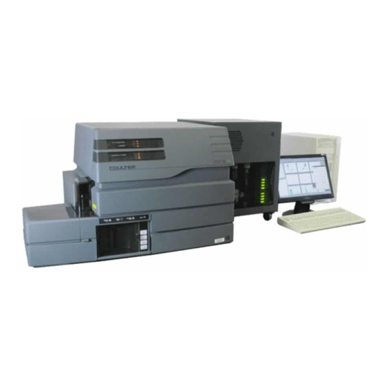
UPDATES FOR YOUR DOCUMENTATION DESCRIPTION OF CHANGES XL and XL-MCL Flow Cytometry System Location of Information Reference Manual: In the Use and Function Chapter under the heading System Components. Getting Started Manual: In the Controls and Indicators Chapter under the heading XL and XL-MCL Flow Cytometry System. -
Page 9: Universal Power Supply
UPDATES FOR YOUR DOCUMENTATION DESCRIPTION OF CHANGES Universal Power Supply Location of Information Getting Started Manual: In the Controls and Indicators Chapter under the heading Power Supply. Figure 2 Universal Power Supply FILTER WATER TRAP TRAP FILTER FILTER Refer to Special WATER TRAP TRAP... -
Page 10: Power And Signal Cable Connections
UPDATES FOR YOUR DOCUMENTATION DESCRIPTION OF CHANGES Power and Signal Cable Connections Location of Information Reference Manual: In the Installation Chapter under the heading System Connections, Power and Signal Cables. Figure 3 Power and Signal Cable Connections, with Universal Power Supply Workstation Cytometer Mouse... -
Page 11: Waste And Pneumatic Tubing Connections
UPDATES FOR YOUR DOCUMENTATION DESCRIPTION OF CHANGES Waste and Pneumatic Tubing Connections Location of Information Reference Manual: In the Installation Chapter under the heading System Connections, Waste and Pneumatic Tubing. Figure 4 Waste and Pneumatic Tubing Connections, with Universal Power Supply Cytometer Flow cell waste... -
Page 12: Cleaning The Air Filters
UPDATES FOR YOUR DOCUMENTATION DESCRIPTION OF CHANGES Cleaning the Air Filters Location of Information Special Procedures and Troubleshooting Manual: In the Cleaning Procedures Chapter under the heading Cleaning the Air Filters. The instrument has four air filters. They are located on the: Cytometer Back Panel Power Supply, Left Side Panel Prepare to Clean the Air Filters... -
Page 13: Cleaning The Vacuum Trap
UPDATES FOR YOUR DOCUMENTATION DESCRIPTION OF CHANGES Cleaning the Vacuum Trap Location of Information Special Procedures and Troubleshooting Manual: In the Cleaning Procedures Chapter under the heading Cleaning the Vacuum Trap. If you have the Universal Power Supply, refer to the following illustration when you do the Clean the Vacuum Trap procedure. -
Page 14: Emptying The Waste Container
UPDATES FOR YOUR DOCUMENTATION DESCRIPTION OF CHANGES Emptying the Waste Container Location of Information Special Procedures and Troubleshooting Manual: In the Replace/Adjust Procedures Chapter under the heading Emptying the Waste Container. SYSTEM POPWER MCL POPWER Adjusting the System Pressure Location of Information Special Procedures and Troubleshooting Manual: In the Replace/Adjust Procedures Chapter under the heading Adjusting the System Pressure. -
Page 15: Resetting The Circuit Breakers
UPDATES FOR YOUR DOCUMENTATION DESCRIPTION OF CHANGES Resetting the Circuit Breakers Location of Information Special Procedures and Troubleshooting Manual: In the Replace/Adjust Procedures Chapter under the heading Resetting the Circuit Breakers. If you have the Universal Power Supply, use the following procedure to reset the circuit breakers. - Page 16 UPDATES FOR YOUR DOCUMENTATION DESCRIPTION OF CHANGES Put the main switch in the 0 position to turn the system off. FILTER WATER TRAP TRAP SYSTEM POWER FILTER MCL POWER PRESS PRESS Reset the circuit breakers by pressing all 26 buttons. FILTER PN 623532AA...
- Page 17 Put the main switch in the 1 position to turn the system back on. FILTER WATER TRAP TRAP SYSTEM POWER FILTER MCL POWER PRESS PRESS Power the computer and cytometer ON. Note: If the problem persists, contact your Beckman Coulter Representative. PN 623532AA...
-
Page 18: Warning Labels On Ups
UPDATES FOR YOUR DOCUMENTATION DESCRIPTION OF CHANGES Warning Labels on UPS Location of Information Reference Manual: In the Precautions and Hazards Chapter under the heading Warning Labels. label located near the circuit breakers on the Universal Power Supply instructs the user to refer to product documentation before resetting the circuit breakers. - Page 19 TRADEMARKS The BECKMAN COULTER logo, COULTER, EPICS, SYSTEM II, XL, and XL-MCL are trademarks of Beckman Coulter, Inc. All other trademarks, service marks, products, or services are trademarks or registered trademarks of their respective holders. PN 623532AA...
- Page 20 ® COULTER EPICS XL and XL-MCL Flow Cytometer Documentation Reference Use and Function • Installation • Operation Principles • PN 4237298 Specifications/Characteristics • Precautions and Hazards • Log Sheets • Predefined Panels, Protocols, and QC Templates • Glossary • Index Special Procedures and Cleaning Procedures •...
Need help?
Do you have a question about the EPICS XL and is the answer not in the manual?
Questions and answers