Table of Contents
Advertisement
Quick Links
Download this manual
See also:
User Manual
Advertisement
Table of Contents

Related Manuals for KVM-TEC Ultraline UVX1


Summary of Contents for KVM-TEC Ultraline UVX1
- Page 1 INSTRuCTION MANuAL 4K uLTRALINE uVX1/uVX1-F KVM EXTENDER Part.No: 6901 Part No: 6902 Ultraline UVX1 UltralineUVX1-F...
-
Page 2: Table Of Contents
2.2.1 Mounting pads and rubber feet 2.2.2 Mounting kits (optional) 2.3 Installing the extender 2.4 Startup 2.5 Replacing the SFP module 2.6 Removing a CAT7 cable 2.7 Removing a fiber cable 3. Extender Settings 3.1 Access Main Menu 2 | kvm-tec... - Page 3 3.1.6 Menu Features 3.1.7 Select keyboard layout 4. Maintenance and care 5. Troubleshooting 6. Disposal 7. Warranty 8. Support 9. Declaration of Conformity 10. Requirements for cables 10.2.1 Requirements for CAT7 cable 10.2.2.Requirements fiber cables 11. Notes kvm-tec | 3...
-
Page 4: Introduction
They contain important information regarding safety, use and disposal for every user of the ultraline uVX1 and uVX1-F KVM Extender. Please familiarise yourself with the information within prior to using your product. use the product only in the manner as described and for the areas of application as stated. -
Page 5: Safety Instructions
Do not use other adapters. • Prior to connecting to the mains, make sure your local mains voltage matches the rating indicated on the product. • The product must be connected to a permanent and earthed AC wall socket. kvm-tec | 5... - Page 6 Unplug all connections before cleaning the product. Do not use wipes or chemicals as these could damage the surface. Wipe the housing with a damp cloth. Electrical/ electronic parts must not be cleaned. • Alterations to the product and technical modifications are not permitted. 6 | kvm-tec...
-
Page 7: Technical Specifications
1. introduction 1.3 TEChNICAL SPECIFICATIONS Type: KVM Extender (local unit-CPU and remote unit-CON) Model: 4K Ultraline UVX1/UVX1-F KVM Extender Power supply input voltage: 90 - 240 V; 50/60 Hz AC Power supply IN: 12V; 2A (external power supply - redundant) -
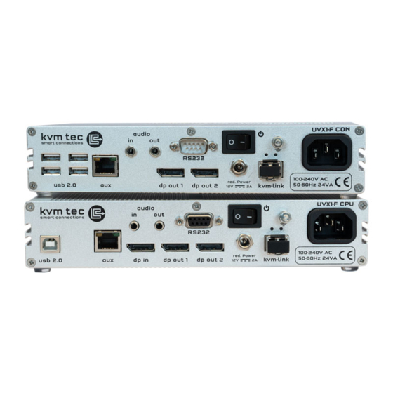
Page 8: Product Elements
2 Displayport Output to Monitor 2 dpout 1 Displayport Output to Monitor 1 dpin DP Input from PC Auxilary Gigabit Network Connector USB 2.0 USB 2.0 to PC POWER/LED status Displays the status of the extender 8 | kvm-tec... - Page 9 Connection für 12V power supply dp out 2 Displayport Output to Monitor 2 dpout 1 Displayport Output to Monitor 1 Auxilary Gigabit Network Connector USB 2.0 to keyboard /Muse POWER/ LED Displays the status of the extender kvm-tec | 9...
-
Page 10: Meaning Of Led Indicators
Fast Update in Progress Green Update Succedded Green V. fast Yes** Red/Green V. fast RJ45 Socket LEDs * Yellow Yellow Slow Green Green V. fast * UVX only ** Rem. Only Table 1: Meaning of LED indicators 10 | kvm-tec... -
Page 11: Installation Of The Extender
D. 1x USB A-B cable 1,8m (5.9ft) E. 2 x Audio cable 1,8m (5.9ft) opt F 1x RS232 cable1,8m (5.9ft) opt. G. 1x Quickstart Manual Manual download www.kvm-tec.com/support H. 8 x rubber feets I. 8x mounting pads UVX -F: 2 x SFP Modul - Multimode up to 300 m ( 984 ft) Manual V 0.01 /14... -
Page 12: Mounting Options
2.2.2 MOuNTING KITS (OPTIONAL) The following mounting kits are available: Rack Mounting Kit RMK-F - Part No. 6230 The rack mounting kit RMK-F is for assembling kvm-tec Ultraline UVX1extenders. It consists of 19“ rack shelf and an alu-faceplate. 12 | kvm-tec... -
Page 13: Installing The Extender
The units can be set up to access one host computer, or to access numerous host computers. In the case of the latter, an additional Network Switch must be installed. With a Network Switch, each user can gain quick access to any of the required computers. Single setup kvm-tec | 13... - Page 14 2. installation of the extender Network Switch Setup 14 | kvm-tec...
- Page 15 • Connect one end of the CAT7 cable (not included) to the kvm-link port (7 /21) on the uVX1/local unit (A). Make sure that the plug is latched. • Connect the other end of the CAT7 cable to the kvm-link port (4) on the uVX1/remote unit (A). Make sure that the plug is latched. kvm-tec | 15...
- Page 16 18. If you are using a Network Switch, connect the Power supply to the AC connection on the Network Switch. 19. Connect a Power cable to uVX1/local unit (6) 20. Connect the other Power cable to uVX1/remote unit (20) . 16 | kvm-tec...
-
Page 17: Startup
2. Pull the metal latch of the SFP+ module forwards until it is at a right angle. 3. Replace the SFP+ module with the other module. Put the metal latch back in position. Only use SFP+ modules from kvm-tec, or recommended by kvm-tec. kvm-tec | 17... -
Page 18: Removing A Cat7 Cable
To remove a CAT7 cable: • Press the latch down and slowly pull the cable out. 2.7 REMOVING A FIBER CABLE To remove a fi ber cable: • Press the latch down and slowly pull the cable out. 18 | kvm-tec... -
Page 19: Extender Settings
In the main menu you can make the following settings by selecting the corresponding letters: Press System status status menu / current status DDC/EDID Settings defi nition of DDC/EDID Update update fi rmware upgrade Menu activated and preinstalled upgrades Features Menu activated features About this device information about the unit kvm-tec | 19... -
Page 20: Status Menu
USB status. The current FW version is displayed in the upper left corner. The link status indicates whether a connection is possible. Video and uSB indicate whether data is currently being transferred. 20 | kvm-tec... -
Page 21: Definition Ddc/Edid Settings
Press ESC to return to the main menu. 3.1.3 DISPLAY uPDATE MENu Display fi rmware version The main menu leads you to the update menu. The currently installed fi rmware version of the remote (CON) and local (CPU) Extender is displayed (e.g.‘0.8‘). kvm-tec | 21... -
Page 22: Firmware Update With Usb Stick
3. EXTENDER SETTINGS 3.1.4 FIRMWARE uPDATE WITh uSB STICK The latest version of the fi rmware can be downloaded at www.kvm-tec.com/ support. Each update fi le includes a detailed description of the update process. For more information, please refer to the update manual. - Page 23 The remote (CON) has now programmed the update. LOCAL uPDATE (CPu) uNIT The update of the local part by pressing „L“ (recommended by kvm-tec) and then a reboot can be performed. To ensure that CON and CPU have the same fi rmware version.
-
Page 24: Upgrade Menu
The already activated Switching upgrade can be activated from the Switching menu (in the main menu). By pressing „S“, you can access the switching menu and thus activate or de-activate the switching upgrade. In the main menu you can configure the switching system with „S“. 24 | kvm-tec... -
Page 25: Menu Features
If this function is active, the Multiview Commander and Mouse Glide features are controlled via the Switching manager software (see Switching Manager manual). All functions of the switching system can be operated via the Matrix Swithcing Mangager software You can download the Switching Manager Software Manual: http://www.kvm-tec.com/en/support/manuals.html kvm-tec | 25... -
Page 26: Select Keyboard Layout
In the Keyboard Layout menu you can switch between the keyboard layouts with which you can navigate the on screen display menu (OSD). Press the K button. The Keyboard Locale menu opens: Press E to select English (QWERTY). Press D to select English (QWERTY). Press F to select French (AZERTY). 26 | kvm-tec... -
Page 27: Maintenance And Care
Loc and (Clicking noise when plugging in) Control both, if it does not work please send an e-mail to support@kvm-tec.com or phone +42 2253 81912 LED is lighting No picture on the Check if the local (PC) cable is connected well. -
Page 28: Troubleshooting
LED is blinking Different fi rmware Please contact the kvm-tec support team via e-mail: green or USB is not support@kvm-tec.com or by phone: +43 2253 81912 30 compatible LED are Different fi rmware To enter on screen menu/check fi... -
Page 29: Warranty
• Damage by lightning Always contact us first before sending back the product. 8. SuPPORT If you have any questions about our products, please contact kvm-tec or your dealer. kvm-tec electronic gmbh kvm-tec Inc Gewerbepark Mitterfeld 1A 67 Camino Del Oro... -
Page 30: Declaration Of Conformity
9. DECLARATION OF CONFORMITY Eu DECLARATION OF CONFORMITY Eu KONFORMITÄTSERKLÄRuNG Hersteller: KVM-TEC Electronic GmbH Gewerbepark Mitterfeld 1A, 2523 Tattendorf, Austria Firmenbuchnummer: FN 272328h LG Wr. Neustadt Hiermit wird erklärt, dass unser Produkt Produkt: Masterline UVX und UVX-F Typ: UVX - Digital KVM Extender UVX-F - Digital KVM Extender Fiber folgende EU-Richtlinien und europäische Normen (EN) erfüllt:... - Page 31 EN 61000-3-2:2014 EN 61000-3-3:2013 EN 60950-1:2006+A2:2013, IEC 60950:2005 LASER CLASS 1: EN 60825-1:2007 kompatibel mit IEEE 803.3z Unterzeichnet für und im Auftrag von: KVM-TEC Electronic GmbH Ort und Datum der Ausstellung: Tattendorf, 2018-05-09 Name, Funktion, Unterschrift: Ing. Dietmar Pfurtscheller, CEO/Geschäftsführer...
-
Page 32: Requirements For Cables
Only use shielded installation cable with min. cross section of 24 AWG throughout the length. • The shield should be contiguous and connected to both ends. A shielded patch cable is allowed for connection to the device. Schema EIA/TIA-568 B Color Orange/White Orange Green/White Blue Blue/White Green Brown/White Brown 32 | kvm-tec... -
Page 33: Requirements For Cat7 Cable
Maximum length should be 300 m (984ft). The MVX1-F includes a fibre Multimode – SFP Module which allows a transmission distance of up to 300 m ( 984 ft) . • Dedicated fibre connection cable type Duplex Multimode 50/125μ (OM2), LC connector kvm-tec | 33... - Page 34 11. NOTES 34 | kvm-tec...
- Page 35 11. NOTES kvm-tec | 35...
- Page 36 11. NOTES 36 | kvm-tec...
- Page 37 | 37...
Need help?
Do you have a question about the Ultraline UVX1 and is the answer not in the manual?
Questions and answers