Advertisement
Quick Links
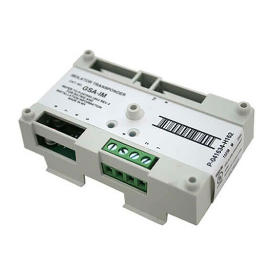
GSA-IM Isolator Module
Installation Sheet
Description
The GSA-IM Isolator Module is an addressable device that protects a
signaling line circuit (SLC) from a wire-to-wire short. The GSA-IM
module monitors line voltages and opens the SLC when a short is
detected, effectively isolating the short between the two isolator
modules located electrically closest to the short.
The GSA-IM module requires one detector address on the SLC.
Addresses are assigned electronically. There are no address switches.
An LED provides visible indication of the status of the module:
•
Normal: Green LED flashes
Installation
Install this device in accordance with applicable national and local
codes, ordinances, and regulations.
•
NFPA 72 2013 – A single fault on a pathway connected to the
addressable devices shall not cause the loss of more than 50
addressable devices.
•
NFPA 72 2016 and later – A single fault on a pathway connected
to the addressable devices shall not cause the loss of the devices
in more than one zone.
Notes
•
The module is shipped from the factory as an assembled unit; it
contains no user-serviceable parts and should not be
disassembled.
•
This module does not operate without electrical power. As fires
frequently cause power interruption, discuss further safeguards
with your local fire protection specialist.
To install the module:
1. Write the address assigned to the module on the label provided,
and then apply the label to the module. Remove the serial number
label from the module, and then attach it to the project
documentation.
2. Wire the module as shown in Figure 2 on page 2.
© 2020 Carrier
3. Using the self-tapping screw provided, attach the wall plate to the
module. See Figure 1.
4. Using the four machine screws provided, attach the wall plate and
module to the electrical box.
Figure 1: Installation diagram
(1) Compatible electrical box
(2) GSA-IM module
(3) Wall plate
Wiring
Wire this device in accordance with applicable national and local
codes, ordinances, and regulations.
Notes
•
Refer to the Signature loop controller installation sheet for SLC
wiring specifications for additional details.
•
All wiring is power-limited and supervised.
To wire the module:
1. Verify that all field wiring is free of opens, shorts, and ground
faults.
2. Strip 1/4 in. (about 6 mm) from the ends of all wires that connect to
the terminal block of the module.
When stripping wire ends, exposing more wire may cause a
ground fault; exposing less wire may result in a faulty connection.
3. Make all wiring connections as shown in Figure 2.
Figure 2: Wiring diagram
SLC
SLC
1 / 3
P/N P-047550-1852-EN • REV 009 • ISS 21FEB20
(1)
(2)
(4) #6-32 × 5/8 machine screws (4X)
(5) #4 × 1/2 self-tapping screw
SLC
SLC
(3)
(4)
(5)
Advertisement

Related Manuals for Kidde GSA-IM


Summary of Contents for Kidde GSA-IM
- Page 1 (4) #6-32 × 5/8 machine screws (4X) (2) GSA-IM module (5) #4 × 1/2 self-tapping screw The GSA-IM Isolator Module is an addressable device that protects a (3) Wall plate signaling line circuit (SLC) from a wire-to-wire short. The GSA-IM...
- Page 2 For Class X pathways (see Figure 5): • Install a GSA-IM module on the Class B out and Class A return wiring inside the control unit, or in the same room, within 20 ft. (6.1 m), and wiring enclosed in conduit or equivalently protected against mechanical injury.
- Page 3 (1) This device may not cause harmful interference, and (2) this device must accept any interference received, including interference that may cause undesired operation. Contact information For contact information, see www.kidde-esfire.com P/N P-047550-1852-EN • REV 009 • ISS 21FEB20 3 / 3...
Need help?
Do you have a question about the GSA-IM and is the answer not in the manual?
Questions and answers