
Related Manuals for Siemens SIMATIC RTU3041C


Summary of Contents for Siemens SIMATIC RTU3041C
- Page 1 Monitoring of Remote Measurement Points using an RTU3041C Siemens SIMATIC RTU3041C / TeleControl Server Basic V3.1 Industry Online https://support.industry.siemens.com/cs/ww/en/view/109739240 Support...
-
Page 2: Legal Information
The foregoing provisions do not imply any change in the burden of proof to your detriment. You shall indemnify Siemens against existing or future claims of third parties in this connection except where Siemens is mandatorily liable. -
Page 3: Table Of Contents
Configuring the GPS functionality of the RTU3041C ......21 Creating tags for programming in the RTU3041C ......24 Creating a program in the SIMATIC RTU3041C ........ 34 Programming email transmission ............37 Configuring the connection to the TeleControl Server ....... 43 2.2.2... -
Page 4: Introduction
1 Introduction Introduction Overview Starting point The battery-powered SIMATIC RTU30X1C is used to monitor and control remote stations that are geographically distributed and not connected to a power supply network. The RTU30X1C can store process data and transmit it to a central station via mobile wireless or via the LAN interface and an external router. - Page 5 1 Introduction Use case The RTU3041C uses an analog level sensor to monitor the level of a rain overflow basin. A digital moisture sensor starts the measurement. In addition, a digital level sensor (float) is installed, which is activated when a critical level is exceeded.
-
Page 6: Principle Of Operation
1 Introduction Principle of Operation Diagram The following figure shows the most important components of the solution schematically: Figure 1-2 Control center TeleControl Server OPC UA Basic Client OPC UA Ethernet Router signal Cell phone RTU3041C Implemented functions The following functions are implemented in the application example: •... -
Page 7: Components Used
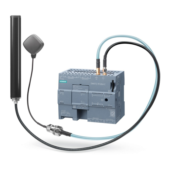
Components Used This application example was created with the following hardware and software components: Table 1-1 Components Quantity Article number Note SIMATIC RTU3041C 6NH3112-4BB00-0XX0 The SIMATIC RTU3031C (6NH3112-3BB00-0XX0) can also be used. Battery module housing 6NH3112-3BA00-1XX2 2 pieces per RTU... -
Page 8: Engineering
6. Connect the analog level sensor to terminal blocks X40 and X41. For instructions on how to operate the SITRANS LU150, refer to the instruction manual: https://support.industry.siemens.com/cs/ww/en/view/109739505. 7. Connect the antennas to the RTU3041C. 8. Connect the battery module housing to the RTU3041C. - Page 9 X10 IN. Note Connection examples for other sensors can be found in the instruction manual: https://support.industry.siemens.com/cs/ww/en/view/109750942. The following table provides an overview of all IP addresses used in this example. Assignment of static IP addresses is assumed. Table 2-1...
-
Page 10: Configuration And Project Planning
2 Engineering Configuration and project planning This section describes the most important steps of the configuration: • Configure the SIMATIC RTU3041C (Section 2.2.1) or load the supplied configuration file (Section 2.2.4) • Configuring the TeleControl Server Basic (Section 2.2.2) •... - Page 11 2 Engineering 5. Log in with the username "admin" and the password "admin". 6. Assign a new password. 7. Navigate to the "System" menu. 8. Assign a unique station name. Monitoring of Remote Measurement Points Entry ID: 109739240, V3.0, 06/2021...
- Page 12 2 Engineering 9. Assign the coordinates for the RTU3041C. 10. Then click "Apply". Monitoring of Remote Measurement Points Entry ID: 109739240, V3.0, 06/2021...
- Page 13 2 Engineering 11. Open the System time tab and select your local time zone. Monitoring of Remote Measurement Points Entry ID: 109739240, V3.0, 06/2021...
- Page 14 2 Engineering 12. Then click "Apply". Note If you are running multiple RTUs on a network, you must assign a unique IP address. Assign an IP address according to your network settings (e.g., 192.168.0.4). 13. To do this, navigate to the "LAN" menu. Monitoring of Remote Measurement Points Entry ID: 109739240, V3.0,...
- Page 15 2 Engineering 14. Enter an IP address and subnet mask. 15. Then click "Apply". Note If you have changed the IP address of the RTU3041C, then open the web server of the RTU3041C again in a browser under the new IP address. Monitoring of Remote Measurement Points Entry ID: 109739240, V3.0,...
- Page 16 2 Engineering 16. Navigate to the "WAN" menu. 17. Open the Mobile wireless settings tab. 18. Enable the mobile function interface. 19. Enter the PIN of the inserted SIM card. 20. Enable the mobile data service. 21. Enter the APN of your mobile operator. If necessary, enter your username and password.
-
Page 17: Configuring Sms/Email Sending/Receiving
2 Engineering Configuring SMS/email sending/receiving To enable the RTU3041C to send messages and data for configurable event classes (diagnostic buffer entries), either as SMS or as email to an operator, proceed as follows: 1. Navigate to the "Users / groups" menu. 2. - Page 18 2 Engineering 11. Add a new group named "Administrator Email". 12. Select the "Email" type. 13. Enable the "Administrator" user. 14. Then click "Apply". 15. Navigate to the "WAN" menu. 16. Open the "SMS" tab. 17. Enable the "Allow receipt of SMS messages" checkbox. 18.
- Page 19 2 Engineering 20. Navigate to the "Services" menu. 21. Open the "E-mail" tab. 22. Enable the "Active" option there. 23. Enter the server data of the email account that the RTU3041C should use to send emails. 24. Then click "Apply". Monitoring of Remote Measurement Points Entry ID: 109739240, V3.0,...
-
Page 20: Configuring Operating Modes
2 Engineering Configuring operating modes To conserve power, the RTU3041C is in sleep mode much of the time, switching to an update or communication mode in predetermined cycles. 1. Navigate to the "Operating mode" menu. 2. Enter the cycle of the update mode e.g., "1 minute" for test purposes or choose"1 hour"... -
Page 21: Configuring The Gps Functionality Of The Rtu3041C
2 Engineering Configuring the GPS functionality of the RTU3041C To enable communication between the RTU3041C and its communication partner via GPS, proceed as follows: 1. Navigate to the "GPS" menu. 2. Open the "General" tab. 3. Enable the "Active" checkbox. 4. - Page 22 2 Engineering To enable the time synchronization via GPS, proceed as follows: 6. Navigate to the "System" menu. 7. Open the "System time" tab. 8. Enable the time synchronization. 9. Select "GPS" as the synchronization method. 10. Then click "Apply". Monitoring of Remote Measurement Points Entry ID: 109739240, V3.0,...
- Page 23 2 Engineering In order to send the determined GPS position of the RTU3041C to the TeleControl Server Basic (TCSB), and to read it out via the OPC UA Client, enable the GPS tags: 11. Navigate to the "GPS" menu. 12. Open the "Tags" tab. 13.
-
Page 24: Creating Tags For Programming In The Rtu3041C
2 Engineering Creating tags for programming in the RTU3041C Before you start programming in the RTU, configure the inputs, outputs, and memory bits. 1. Navigate to the "Tags" menu. 2. Open the "Digital inputs" tab. 3. Click on input 0. 4. - Page 25 2 Engineering 11. Select that an additional update cycle is also performed in sleep mode when the value changes. 12. Then click "Apply". 13. Open the "Digital memory bits" tab. 14. Click on the 0 memory bit. 15. Enable the "Active" checkbox. 16.
- Page 26 2 Engineering 22. Click memory bit 2. 23. Enable the "Active" checkbox. 24. Assign the name "gpsPosition". 25. Then click "Apply". 26. Open the "Analog inputs" tab. 27. Click the analog input 0. 28. Enable the "Active" checkbox. 29. Assign the name "fillLevel". Monitoring of Remote Measurement Points Entry ID: 109739240, V3.0,...
- Page 27 2 Engineering 30. Select the measurement type of your analog level sensor. The SITRANS Probe LU150 sensor must be set to "Current (2-wire connector)". 31. Enter the settling and integration time as well as the smoothing of the signal of your sensor.
- Page 28 2 Engineering Note This setting means that the analog input "fillLevel" is only read if the digital input "enableReadFillLevel" is activated. This can significantly reduce power consumption. 34. Enable the "Diagnostics messages" to diagnose the errors. 35. Then click "Apply". 36.
- Page 29 2 Engineering 44. Enable the "Active" checkbox. 45. Assign the name "fillLevelPercent". 46. Select the type "Analog value". 47. Then click "Apply". 48. Click on the analog memory bit 2. 49. Enable the "Active" checkbox. 50. Assign the name "distance". Monitoring of Remote Measurement Points Entry ID: 109739240, V3.0,...
- Page 30 2 Engineering 51. Select the type "Analog value". 52. Then click "Apply". Configuring texts for SMS/email dispatch 1. Open the "Texts" tab. 2. Add a new text to be sent via SMS and email when the critical level is exceeded: –...
- Page 31 2 Engineering – Date: [DATE] – Time: [TIME] 3. Then click "Apply". 4. Add a new text to be sent when the critical level is exceeded in the subject of the email: – Name: subCritLevelReached – Text: Critical fill level reached at station x 5.
- Page 32 2 Engineering 8. Add a new text to be sent when the level falls below the critical level in the subject of the email: – Name: subFillLevelFallen – Text: Fill level at station x has fallen below critical level 9. Then click "Apply". 10.
- Page 33 2 Engineering 12. Add a new text to be sent by SMS when the RTU3041C moves outside a parameterized radius: – Name: gpsPositionNotOK – Text: The last known GPS position is outside the tolerance radius. – Date: [DATE] – Time: [TIME] 13.
-
Page 34: Creating A Program In The Simatic Rtu3041C
2 Engineering Creating a program in the SIMATIC RTU3041C In order for the RTU3041C to respond appropriately to events, you must create a program. Programming is comparable to "FBD" in the TIA Portal. Program comparison of the current level with a critical value 1. - Page 35 2 Engineering 7. Select "Limit value switch" as the function. 8. Interconnect the parameters as follows: – Input: fillLevelPercent (AM1) – Output: fillLevel90 (DM0) – Limit value 1: 0.9000 – Limit value 2: 0.8999 9. Add a new function block (FB3) below. Monitoring of Remote Measurement Points Entry ID: 109739240, V3.0,...
- Page 36 2 Engineering 10. Select "Logical OR" as the function. 11. Interconnect the parameters as follows: – Input 1: float (DI0) – Input 2: fillLevel90 (DM0) – Output: critFillLevel (DM1) 12. Negate input 1. 13. Then click "Apply". Monitoring of Remote Measurement Points Entry ID: 109739240, V3.0, 06/2021...
-
Page 37: Programming Email Transmission
2 Engineering Programming email transmission 14. Add a new network. 15. Assign the name "Send email" to the network. 16. Add a new function block (FB1). 17. Select "Send email" as the function. 18. Interconnect the parameters as follows: – Trigger: critFillLevel (DM1) –... - Page 38 2 Engineering 19. Add a new function block (FB2). 20. Select "Send email" as the function. 21. Interconnect the parameters as follows: – Trigger: critFillLevel (DM1) – Send immediately: True – Recipient: Administrator email – Text: fillLevelFallen – Subject: subFillLevelFallen 22.
- Page 39 2 Engineering Programming SMS transmission 24. Add a new network. 25. Assign the name "Send SMS" to the network. 26. Add a new function block (FB1). 27. Select "Send SMS" as the function. 28. Interconnect the parameters as follows: – Trigger: critFillLevel (DM1) –...
- Page 40 2 Engineering 30. Select "Send SMS" as the function. 31. Interconnect the parameters as follows: – Trigger: critFillLevel (DM1) – Send immediately: True – Recipient: Administrator SMS – Text: fillLevelFallen 32. Negate the "Trigger" input. 33. Then click "Apply". Programming GPS position 34.
- Page 41 2 Engineering 36. Add a new function block (FB1). 37. Select "GPS position" as the function. 38. Interconnect the parameters as follows: – Postion: System location – Radius (m): 1000 – Output: gpsPosition (DM2) – Distance: distance (AM2) 39. Add a new function block (FB2) below it. 40.
- Page 42 2 Engineering 42. Add a new function block (FB3) below. 43. Select "Send SMS" as the function. 44. Interconnect the parameters as follows: – Trigger: gpsPosition (DM2) – Send immediately: True – Recipient: Administrator SMS – Text: gpsPositionNotOK 45. Negate the "Trigger" input. 46.
-
Page 43: Configuring The Connection To The Telecontrol Server
2 Engineering Configuring the connection to the TeleControl Server A connection to the TeleControl Server must be established so that the RTU3041C can reach the TeleControl Server. 1. Navigate to the "TeleControl" menu. 2. Open the "TeleControl Basic" tab. 3. Enable the "Active" checkbox. 4. - Page 44 2 Engineering 6. Enter the IPT listener port of the TeleControl server that you have enabled in your router (55097 by default) as the port number. 7. Enter – a unique project number – a unique station number and – a TeleControl password.
- Page 45 2 Engineering 9. Open the Data points tab. 10. Set the following settings for the digital input "float (DI0)": – Transmission method: (Event (only current values)) – Trigger: Change – Transfer mode: Buffered transfer 11. Set the following settings for the digital input "enableReadFillLevel (DI1)": –...
- Page 46 2 Engineering 15. Set the following settings for the analog input "gpsLatitude (GPS0)": – Transmission method: (Event (only current values)) – Trigger: Change – Transfer mode: Buffered transfer 16. Set the following settings for the analog input "gpsLongitude (GPS1)": – Transmission method: (Event (only current values)) –...
-
Page 47: Configuring The Telecontrol Server Basic
2 Engineering 2.2.2 Configuring the TeleControl Server Basic To configure the TeleControl Server Basic, proceed as follows: 1. Open the program "CMT - Configuration and Monitoring Tool" on your PG/PC. TeleControl Server Basic must be installed on the PG/PC. 2. Log in with your user data. The following user data is preset at the factory: –... - Page 48 2 Engineering 5. Assign a project name and a server password with which Engineering Stations can connect to the TeleControl server. – The server password is not relevant for this application example but must be assigned. – The SMS gateway operator is not relevant for this application example. Note The parameter "Project number"...
- Page 49 2 Engineering 9. Enter – a station name – a unique station number and – a TeleControl password. Note The parameters "Station number" and "TeleControl password" must match the parameters in Section 2.2.1 in the configuration of the connection to the TeleControl Server (Step 10.
- Page 50 2 Engineering 12. Configure the IP address and the IPT listener port (55097) of the TeleControl server: "TCSB system > "TCM" tab > General> Address TCM 1". The "55097" must be enabled for communication in your DSL router. Note The configuration of the TeleControl Server is now completed. Note The status "Connected"...
-
Page 51: Configuring Opc Ua Clients (Uaexpert)
2 Engineering 2.2.3 Configuring OPC UA Clients (UaExpert) This section explains how to monitor the data points of the TCSB via OPC UA. The following is required to use the OPC UA Client "UaExpert": – "UaExpert" is installed on your PC. –... - Page 52 2 Engineering 4. In the following dialog, enter the URL and the port of the OPC UA Server (TCSB) (e.g., opc.tcp://192.168.0.100:4852). 5. Click on "OK". 6. Select an endpoint of the OPC UA Server to which you want to establish a connection (for example: OPC.SimaticNET.TCSB (opc.tcp)/ None -None).
- Page 53 2 Engineering 7. Enter the user data for the "CMT - Configuration and Monitoring Tool". 8. Set the "Connect Automatically" checkbox. 9. Then confirm with "OK". 192.168.0.100:4852 10. In the following dialog, accept the server certificate by setting the checkbox "Accept the server certificate temporarily for this session".
- Page 54 2 Engineering 11. Then click "Continue". 12. Then locate the desired data points and drag them into the "Data Access view" window. Result: Monitoring of Remote Measurement Points Entry ID: 109739240, V3.0, 06/2021...
-
Page 55: Loading The Configuration File
2 Engineering 2.2.4 Loading the Configuration File The supplied archive "109739240_RTU3041C_ PROJ_V30.zip" contains the finished configuration file ("*.cfg"), which you can load into your RTU3041C and adapt to your application in just a few steps. To load the supplied configuration into your RTU3041C, proceed as follows: 1. - Page 56 2 Engineering 11. Click "Load on device". 12. The previously set password is overwritten with the password "RTU3041c!" stored in the configuration file. 13. Navigate to the "System > General" menu. 14. Assign the coordinates for your RTU3041C. 15. Then click "Apply". Monitoring of Remote Measurement Points Entry ID: 109739240, V3.0,...
- Page 57 2 Engineering 16. Navigate to the "Operating mode" menu. 17. Enter the minimum duration of the service mode (e.g., "30 seconds") for the application described here. 18. Then click "Apply". 19. Navigate to the "Users / groups" menu. Monitoring of Remote Measurement Points Entry ID: 109739240, V3.0, 06/2021...
- Page 58 2 Engineering 20. Enter the phone number with country code (e.g., "+49" for Germany). 21. Enter the email address for the "Administrator" user. 22. Change the password. 23. Then click "Apply". Monitoring of Remote Measurement Points Entry ID: 109739240, V3.0, 06/2021...
- Page 59 2 Engineering 24. Navigate to the "WAN" menu. 25. Open the Mobile wireless settings tab. 26. Enter the PIN of the inserted SIM card. 27. Enter the APN of your network operator. 28. Then click "Apply". Monitoring of Remote Measurement Points Entry ID: 109739240, V3.0, 06/2021...
- Page 60 2 Engineering 29. Navigate to the "Services" menu. 30. Open the "Email" tab. 31. Enter the server data of the email account that the RTU3041C should use to send emails. 32. Then click "Apply". 33. Navigate to the "TeleControl" menu. 34.
-
Page 61: Operation
2 Engineering Operation 2.3.1 RTU3041C Wake-Up by Mobile Phone To read current process values, you can wake the RTU from sleep mode between two communication cycles. 1. To do this, send an SMS with the text "TELESERVICE" to the mobile phone number of the SIM card inserted in the RTU3041C. -
Page 62: Determining The Exact Position Of The Rtu3041C Via Gps
2 Engineering 2.3.2 Determining the Exact Position of the RTU3041C via GPS The exact position of the RTU3041C can be monitored via GPS. This section shows you how to determine the exact position of your RTU3041C via GPS. For this scenario, the following is assumed: –... -
Page 63: Useful Information
3 Useful Information Useful Information 3.1.1 Update and Communication Mode The RTU cyclically changes from sleep mode to update or communication mode. The frequency of the update and communication cycles can be defined. Figure 3-1: Parameterization of the operating mode Update mode In update mode, the RTU goes through the following steps: –... - Page 64 3 Useful Information Configurable events In addition to the configured update cycle, the RTU switches from sleep mode to update mode when configurable events occur. You can configure the following events: – Value change at analog input "AI0" – Edge change at a digital input –...
- Page 65 3 Useful Information Communication mode In communication mode, the RTU performs the following tasks: – Sending the data telegrams to the configured communication partner in the control center – Sending saved messages (SMS, emails) – Synchronization of the time (if configured) In addition to the previously mentioned tasks, a connection from the TeleControl server or the configuration PC to the WBM of the RTU can be established in communication mode.
- Page 66 3 Useful Information Transfer after call The current value of the data point is stored in the RTU. New values of a data point overwrite the last stored value. In communication mode, the current value at that time is transmitted. Event (current value) If the transmission type "Event"...
-
Page 67: Appendix
Industry Online Support Do you have any questions or need assistance? Siemens Industry Online Support offers round the clock access to our entire service and support know-how and portfolio. The Industry Online Support is the central address for information about our products, solutions and services. -
Page 68: Industry Mall
4 Appendix Industry Mall The Siemens Industry Mall is the platform on which the entire siemens Industry product portfolio is accessible. From the selection of products to the order and the delivery tracking, the Industry Mall enables the complete purchasing processing –... -
Page 69: Change Documentation
4 Appendix Change documentation Table 4-2 Version Date Change V1.0 10/2016 First version • V2.0 01/2019 Migration to TeleControl Server Basic V3.1 • Using UaExpert as OPC UA Client V3.0 06/2021 Expansion with the GPS functions of a RTU30x1C: • Time synchronization •...
Need help?
Do you have a question about the SIMATIC RTU3041C and is the answer not in the manual?
Questions and answers