Advertisement
Advertisement
Table of Contents

Related Manuals for UMF Medical 4040-650


Summary of Contents for UMF Medical 4040-650
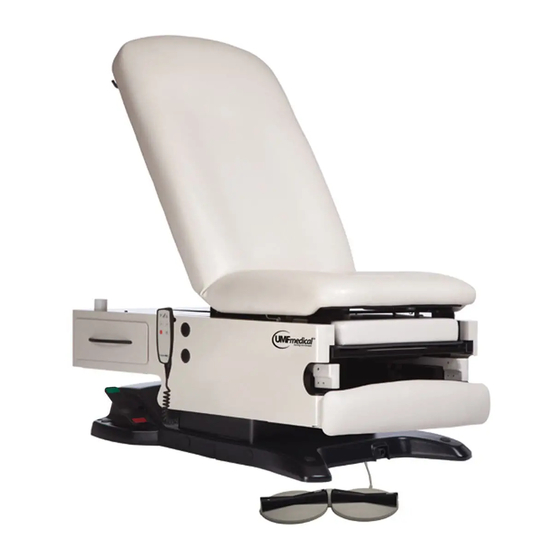
- Page 1 Moving Care FORWARD 4040-650/4070-650 Power Exam Table Owner’s Manual Serial number: Date of Manufacture: Maximum Patient Weight: 650 lbs / 295 kg 1316 Eisenhower Boulevard - Johnstown, PA 15904, USA - 800-638-5322 - CustomerService@UMFMedical.com - www.UMFMedical.com 3-00077-0318A...
-
Page 2: Safety Symbols
3. This manual should remain permanently affixed or near the equipment for convenient reference. 4. UMF Medical reserves the right to make changes to the design of products at any time and without notice. CLASSIFICATIONS Equipment Class – Class I... -
Page 3: Specifications
SPECIFICATIONS (4040-650) Maximum Patient Weight ....650 lbs (295 kg) Electrical Supply(Standard) ....120V 60HZ 9AMP Electrical Supply(Optional) ....220V 60HZ 5AMP Power Cord Length ......Powe 10 FT (3.0m) Table Weight .......... Table 400 lbs (181kg) Paper Roll (Maximum size) .... - Page 4 SPECIFICATIONS (4070-650) Maximum Patient Weight ....650 lbs (295 kg) Electrical Supply(Standard) ....120V 60HZ 9AMP Electrical Supply(Optional) ....220V 60HZ 5AMP Power Cord Length ......10 FT (3.0m) Table Weight .......... Tabl 400 lbs (181kg) Paper Roll (Maximum size) ....Pape 21.0”...
-
Page 5: Safety Features
SAFETY FEATURES PATIENT SAFETY TABLE LOCKOUT 4040-650 This table is equipped with a safety feature that allows the practitioner to deactivate all table functions in order to prevent misuse when staff is not present. To lock and unlock: Press & hold STOP button for 2 seconds. -
Page 6: Features And Operation
FEATURES AND OPERATION HAND & FOOT CONTROL - TABLE OPERATION (4040-650) Hand Control Hand Control Foot Control Foot Control Height Height Home Home Adjustment Adjustment Backrest Adjustment WARNING: DO NOT USE BACKREST AS A SEAT Page 6 3-00077-0318A... - Page 7 FEATURES AND OPERATION HAND & FOOT CONTROL - TABLE OPERATION (4070-650) Hand Control Hand Control Foot Control Foot Control Height Height Home Home Adjustment Adjustment Backrest Adjustment (Manual Operation) 1. Depress release handle. 2. Adjust backrest to desired position. 3. Release handle to lock. WARNING: DO NOT USE BACKREST AS A SEAT...
- Page 8 HAND CONTROL - MEMORY PROGRAMMING & SPECIAL FUNCTIONS Simultaneous Movement (shown as an example) Memory Positions Stop Control 4040-650 4070-650 - Two programmable positions for storing commonly use table positions. To Program: 1) Move table to desired position for memory storage.
- Page 9 (4070-650:) by squeezing the until all latches align properly. manual release lever and gently lifting upward. (4040-650:) by using hand or foot control. STEP 5: STEP 6: Using your index finger, slide all Raise the foot section of the...
-
Page 10: Storage Drawers
FEATURES AND OPERATION STORAGE DRAWERS SIDE DRAWER 24.5” x 12.5” x 3.5” (62cm x 32cm x 9cm) FRONT DRAWER 19.0” x 12.0” x 3.5” (48cm x 30cm x 9cm) LEG EXTENSION & DRIP PAN 1. Slide the leg section out. 2. -
Page 11: Paper Roll Replacement
FEATURES AND OPERATION PAPER ROLL REPLACEMENT Max Roll Size..21” x 3.5” (53cm x 9cm) Slide rod out of brackets, install new roll, and reinstall into brackets STIRRUP POSITIONING & ADJUSTMENT 1. Pull the stirrups out and unfold. 2. Lift slightly and move left or right to position. 3) Release stirrup to lock into position. - Page 12 FEATURES AND OPERATION REVERSING SIDE DRAWERS STEP 1: STEP 2: Remove side panels. Remove drawer - Extend drawer - Press tabs on both sides - Remove drawer STEP 3: STEP 4: Slide cages to opposite side Align slides and install of table drawer on opposite side.
- Page 13 COMMON OPTIONS AND ACCESSORIES MOBILE CASTER BASE (142) Concealed retractable casters can be installed on base to allow for easy table movement for cleaning. WARNING: TABLE IS NOT TO BE USED FOR PATIENT TRANSPORT. ENSURE WHEELS ARE IN ‘PATIENT READY’ POSITION PRIOR TO A PATIENT ACCESSING TABLE.
- Page 14 COMMON OPTIONS AND ACCESSORIES HOSPITAL GRADE RECEPTACLE WITH CHILD SAFE COVER (852) 1. To access receptacles, insert a screwdriver, key, or other tool into slot on receptacle cover to remove child-proof cover 2. Replace child-proof cover following use Option available on the 200 series and standard on the 300 series. WARNING: OUTLET IS FOR MEDICAL EQUIPMENT ONLY.
- Page 15 COMMON OPTIONS AND ACCESSORIES BIERHOFF KNEE CRUTCH (251-PAIR) 1. Extend stirrups to full-extended position with heel stirrup in retracted position. 2. Insert knurled end of knee crutch rod into hole on end of stirrup 3. Adjust to position and tighten with slide lock. STAINLESS STEEL IRRIGATION PAN WITH SPOUT (822) The stainless steel drain pan is offered without a spout (standard) or with spout (optional - shown...
-
Page 16: Cable Connection
CABLE CONNECTION Front 1. Optional Port for foot or hand control Back (Left to Right) 1. Port for foot control 2. Port for hand control 3. LED 4. Port for power cord Cable Locking Feature 1. Plug into the hand control port 1. -
Page 17: Equipment Care
*** See current CDC Guideline for Disinfection & Sterilization in Healthcare Facilities for bleach alternative cleaners Note: Immediately remove any fluid spilled on upholstery surface. Antimicrobial: UMF Medical Upholstery providers outstanding protection in difficult medical and healthcare environments and contains an agent effective against bacterial and fungal microorganisms. -
Page 18: Warranty Information
LIMITED TO THE REPAIR OR REPLACEMENT OF DEFECTIVE PARTS. No action may be brought against UMF Medical for breach of this limited warranty, an implied warranty, if any, or for any other claim arising out of or relating to the products following expiration of the limited warranty period. -
Page 19: Setup Instructions
SETUP INSTRUCTIONS Models 4040/4070-650-100 (Power100+, Power100) To Set Up your New Power Table: PLEASE FOLLOW THESE STEPS COMPLETELY to Ensure that your table functions properly PLEASE DO NOT PLUG TABLE IN UNTIL PRECEDING STEPS ARE COMPLETED The Table has one (1) Port for the Foot Control in the Front of the Table Base. Locate the Plug Port in the Front of the Table Base.
Need help?
Do you have a question about the 4040-650 and is the answer not in the manual?
Questions and answers